Lighting / Fixtures
Installation Guide for Juno Slimform LED Downlight
A comprehensive installation guide for Juno Slimform LED downlights. Includes step-by-step mounting instructions, wiring diagrams, color temperature settings, and troubleshooting tips.
Table of contents
Manual images
Click an image to enlargeQuick Guide
The Juno Slimform LED downlight is designed for installation in UL-listed junction boxes. Before beginning, ensure the power is turned off at the circuit breaker. The fixture features an adjustable color temperature switch on the back and requires specific arrow alignment for secure installation.
Important Safety Information
- Installation and service must be performed by a qualified licensed electrician.
- Disconnect power before installation or servicing.
- Ensure the junction box is properly grounded.
- Do not install damaged products.
- The fixture is suitable for damp locations; wet locations require sealing with silicone caulk.
Installation Steps
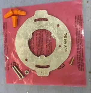
- Preparation: Verify all parts are included: LED module, mounting bracket, wirenuts, screws, and nut.
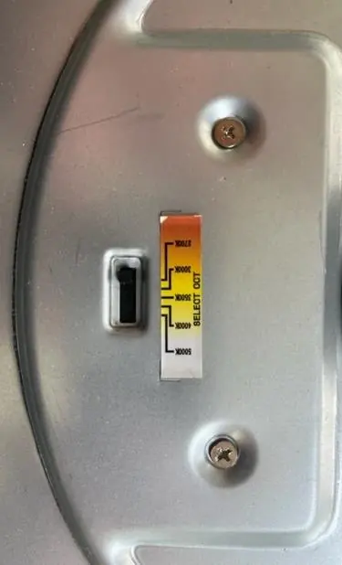
- Color Temperature: Move the switch on the back of the fixture to the desired color temperature setting before installation.
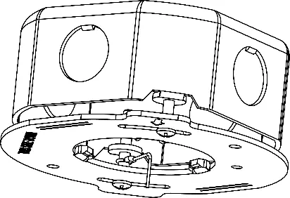
- Mounting Bracket: Secure the mounting bracket to the junction box using the provided #8 screws. Ensure the side labeled "THIS SIDE DOWN" faces the floor. For square fixtures, align the straight edge of the bracket parallel to the wall.
- Tether Cable: Attach the tether cable eyelet using the 12mm screw (Method A) or by securing it under one of the mounting screws (Method B).
- Wiring: Connect the bare copper ground wire from the fixture to the junction box ground wire. Connect the black fixture wire to the black power supply wire and the white fixture wire to the white power supply wire using wirenuts.
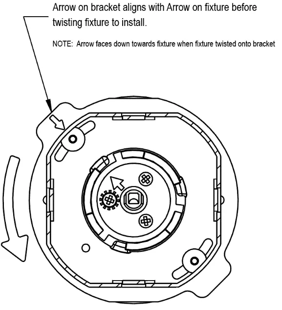
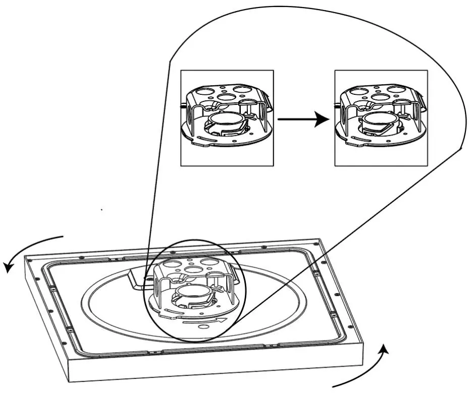
- Final Assembly: Position wires into the outlet box. Align the straight arrow on the mounting puck with the straight arrow on the mounting bracket. Twist the fixture clockwise while pushing upwards until you feel a "bump" to lock it in place.
Wiring and Dimming
For fixtures with 0-10V dimming (120-277V drivers), connect the violet dimmer wire (+) to the positive dimmer wire and the pink dimmer wire (-) to the negative dimmer wire. Ensure all connections are capped with UL-approved wire connectors.
Troubleshooting
If the fixture fails to operate:
- Verify that the fixture is wired properly.
- Ensure the fixture is grounded correctly.
- Check that the line voltage at the fixture is correct.
For further assistance, contact Technical Support at (800) 705-7378.
Practical help
Common problems
Fixture fails to operate
Verify proper wiring, correct grounding, and that the line voltage is correct.
Gap between fixture and ceiling
Ensure the junction box is not protruding from the ceiling surface.
Before use
- Turn off electricity at the fuse or circuit breaker box.
- Verify the junction box is UL listed and at least 1 3/4" deep.
- Ensure there is at least 3" of clearance space in the junction box.
- Set the desired color temperature switch on the back of the fixture.
Specs in practice
- 0-10V Dimming
- Requires a compatible 0-10V dimmer for universal voltage drivers.
- Color Temperature Switch
- Allows selection of different light color temperatures before installation.
Images and diagrams
- Figure 2: Location of the color temperature selection switch.
- Figure 3: Proper alignment of the mounting bracket relative to the wall.
- Figure 7: Alignment of arrows on the fixture and bracket required for installation.
- Figure 8: Twisting motion required to lock the fixture into the mounting bracket.
Model compatibility
- Compatible with 4" octagonal junction boxes (metal or plastic).
- Compatible with Juno IC1JB 4" junction box.
- 120V fixtures must be connected to 120V power; 120-277V fixtures to 120-277V power.

Manual page author
Emily Carter
User documentation editor
Prepares concise manual descriptions and highlights the most useful setup, operation, and maintenance information for readers.