Lighting / Fixtures
Pathway PWINF DIN CC 12-Channel Contact Closure Interface Manual
Quick guide for the Pathway PWINF DIN CC 12-Channel Contact Closure. Learn about wiring, DMX configuration, operating modes, and status indicators for this DMX-controlled relay interface.
Table of contents
Manual images
Click an image to enlargeQuick Guide
The Pathway PWINF DIN CC is a 12-channel DMX-controlled relay interface designed for DIN-rail mounting. It provides form-C relay closures for low-voltage power or signal switching. Key setup steps include connecting power (9-30VDC), wiring DMX512 data, and configuring the operating mode via the onboard user interface.
Overview
The module features twelve DMX-controllable switch closures. Each relay has three sets of contacts: normally-open (NO), normally-closed (NC), and common (C). The unit is RDM discoverable and configurable.
Connections
Important: Always perform wiring with the power turned off.
- Power: Connect 9-30VDC to the V+ and V- terminals. Observe correct polarity. A second set of terminals allows for daisy-chaining power to other DIN modules. Connect the EARTH GROUND terminal to the chassis or electrical ground for EMC compliance.
- DMX512: Connect the shield and data pair. Connect DATA+ and DATA- to D1+ and D1- respectively for both DMX IN and DMX THRU. Connect the cable shield to the SHLD COM terminal.
- Contact Outputs: Each relay provides independent NO, NC, and C contacts. These switches provide no voltage or current on their own; they act as a switch between the supply and the load.
- DMX Present Relay Closure: Starting with firmware 1.5.5, wire RCOM to RNO or RNC for normally-open or normally-closed operation.
Status Indicators
- POWER IN (Blue): Steady glow indicates power supply is OK.
- PROCESSOR (Green): Steady glow indicates processor is OK.
- DMX INPUT (Amber): Steady glow indicates port is latched to an active DMX source.
- RELAY (Red): Steady glow indicates relay is energized.
- FUNCTION (Amber): Indicates the function associated with the numeric display.
Configuration and Operating Modes
The user interface has two modes: Function and Edit. Use the ▲ or ▼ buttons to select a function (ADDRESS, MODE, UTIL, TEST). Press and hold ENTER until a dot appears in the lower right-hand corner to enter EDIT mode.
Operating Modes
- Mode 1 (12-Channel Maintained Control): Relay is "on" while DMX value is above 50%.
- Mode 2 (12-Channel Momentary Control): Relay closes for 100mS when DMX passes 50% threshold.
- Mode 3 (12-Channel Momentary ON): Relay closes for 100mS when DMX increases past 50%.
- Mode 4 (6-Channel Momentary Split): Adjacent pairs associated with one DMX channel.
- Mode 5 (6-Channel Maintained Split): Adjacent pairs associated with one DMX channel.
- Mode 6 (12-Channel Momentary Split with Secondary Reset): Uses 2 sequential DMX channels per pair.
- Mode 7 (Chase): Test feature; each relay triggers for two seconds.
- Mode 8 (Single Channel Select): DMX level determines which single relay is maintained.
- Mode 9 (Single Channel Build): DMX level determines how many relays are triggered.
DMX Termination
If the device is the last on the DMX line, the DMX Terminate switch must be set to ON to prevent signal reflection. If other devices are connected to the DMX THRU terminal, the switch must be OFF.
Technical Specifications
- Input Voltage: 9-30VDC
- Power Consumption: 6W
- Relay Rating: 2A @ 30VDC (minimum 100,000 operations)
- Operating Temperature: 14°F to 113°F (-10°C to 45°C)
- Compliance: ANSI E1.11 DMX512-A, ANSI E1.20 RDM, RoHS, CE
Practical help
Common problems
Processor LED is off
Check that the power supply is connected correctly (9-30VDC) and that the power source is active.
No DMX signal detected
Ensure the DMX cable is wired correctly (D1+, D1-, SHLD) and that the DMX source is active.
Relay not triggering
Verify the operating mode settings and ensure the DMX level is above the 50% threshold (for maintained modes).
Before use
- Ensure power is turned OFF before making any wiring connections.
- Verify power supply is 9-30VDC.
- Connect Earth Ground to the enclosure chassis.
- Set the DMX Terminate switch to ON if this is the last device in the DMX chain.
- Ensure DMX polarity is consistent throughout the system.
Specs in practice
- Relay Rating
- Maximum load capacity is 2A at 30VDC.
- Power Consumption
- The unit consumes 6W of power.
- Operating Conditions
- Operates between 14°F-113°F (-10°C-45°C) and 5-95% relative humidity.
Images and diagrams
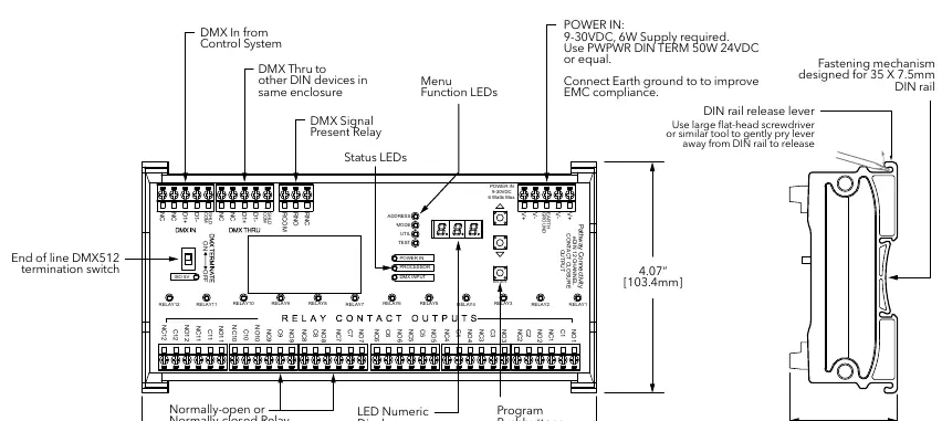
- The wiring diagram illustrates the terminal strip layout for DMX IN, DMX THRU, and the 12 Relay Contact Outputs.
- The diagram highlights the location of the DMX Terminate switch and the DIN rail release lever.
Model compatibility
- Fully compliant with ANSI E1.11 DMX512-A R2013.
- Fully compliant with ANSI E1.20 RDM (Remote Device Management).
- Firmware 1.5.5 and higher supports J13 DMX present relay closure.

Manual page author
Emily Carter
User documentation editor
Prepares concise manual descriptions and highlights the most useful setup, operation, and maintenance information for readers.