Automotive / Car Audio
Installation, Operation and Maintenance Manual for ACV HeatMaster 200 N and 200 F
Comprehensive installation, operation, and maintenance guide for the ACV HeatMaster 200 N and 200 F boilers. Includes setup, safety instructions, technical specifications, and troubleshooting.
Quick answers from the manual
Quick answer
- The HeatMaster 200 N/F is a commercial boiler. Installation and maintenance must be performed by a qualified engineer. The user guide covers control panel operation, pressure management, and basic troubleshooting. p. 1, 3
Key actions
- Resetting the burner p. 5
- Filling the heating circuit p. 14
First start
- Ensure the system is filled and pressurized, then set the master switch to ON. p. 14
Problems and fixes
Burner lockout
Wait 5 minutes, press reset button on burner.
p. 5Maintenance and reset
- Resetting high limit thermostat: Allow boiler to cool below 60°C, unscrew cap, and press reset button. p. 4
Technical specifications
| Parameter | Value | Meaning | Pages |
|---|---|---|---|
| Operating voltage | 230V | Standard electrical supply | p. 10 |
Where to find it in the PDF
- Control Panel p. 4
- Installation p. 11, 12, 13
Table of contents
Manual images
Click an image to enlargeQuick guide from the manual
The ACV HeatMaster 200 N and 200 F are high-efficiency boilers designed for industrial use. This manual provides essential instructions for installation, operation, and maintenance. Important: Installation and servicing must be performed by a qualified engineer. Always isolate the electrical supply before performing any work on the unit.
Appliance Description
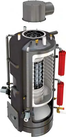
The HeatMaster 200 series features a stainless steel tank and is designed for both domestic hot water (DHW) and central heating. Key components include the burner chamber, flue gas tubes, primary expansion vessels, and a control panel for monitoring temperature and pressure.
Installation and Connections
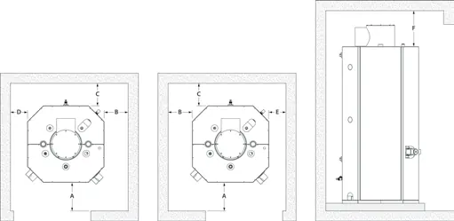
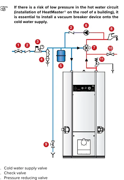
The appliance is delivered in multiple packages. Ensure the base is made of non-combustible materials. Connections must comply with local standards. The DHW tank must be pressurized before the primary heating circuit. For heating connections, ensure the expansion vessels are sized correctly for the total system volume. The primary safety valve must be connected to the sewer using a metallic pipe.
Operation and Control Panel
The control panel allows for monitoring and basic operation:
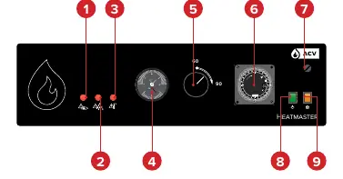
- Master switch: Turns the boiler on or off.
- Control thermostat: Sets the temperature (60-90°C).
- Temperature and pressure gauge: Indicates system status. Pressure should not fall below 0.1 MPa (1 bar).
- Manual reset high limit thermostat: If the boiler exceeds 103°C, this safety device activates. Allow the boiler to cool before resetting.
- Daily timer: Allows for 24-hour scheduling.
Maintenance and Safety
Annual maintenance by a qualified engineer is required. This includes cleaning the flue gas tubes, checking the burner, and testing safety devices. If the burner locks out, wait 5 minutes before pressing the reset button. Always ensure the system is properly drained before maintenance; water from the drain valve may be extremely hot.
Technical Specifications
The HeatMaster 200 N is compatible with oil or gas burners, while the 200 F is factory-equipped with a Riello RG4S oil burner. Maximum operating temperature is 90°C. Water quality must be maintained with chlorides ≤ 150 mg/l and pH between 6 and 8.
Practical help
Common problems
Burner lockout
Wait 5 minutes, then press the reset button located on the burner.
Low primary water pressure
Top up the heating circuit via the filling valve until the gauge indicates the required pressure (min 0.1 MPa/1 bar).
High temperature safety lockout
Allow the boiler to cool below 60°C, unscrew the cap, and press the reset button.
Before use
- Verify package contents are free of damage.
- Ensure installation is performed by a qualified engineer.
- Check that all air vents are unobstructed.
- Verify gas/oil supply is connected and operational.
- Ensure the DHW tank is pressurized before the heating circuit.
Specs in practice
- Primary circuit pressure
- Minimum 0.1 MPa (1 bar) when cold.
- DHW circuit pressure
- Maximum 0.86 MPa (8.6 bar).
- Operating temperature
- Adjustable between 60°C and 90°C.
Images and diagrams
- Control panel layout showing indicators and switches.
- Wiring diagram for electrical connections.
- DHW and heating connection diagrams for various configurations.
Model compatibility
- HeatMaster 200 N: Compatible with various oil or gas burners.
- HeatMaster 200 F: Factory-fitted with Riello RG4S oil burner.

Manual page author
Michael Turner
Technical manual editor
Reviews PDF manuals for structure, safety notes, and practical product details so readers can find the right information quickly.