General / Other Manuals
AKO 1652H4A11 Advanced Temperature Controller for Cold Rooms
User guide for the AKO-16524A, AKO-16525A, and AKO-16525AN advanced temperature controllers, covering installation, configuration, operation, and troubleshooting.
Table of contents
Product Overview
The AKO-16524A, AKO-16525A, and AKO-16525AN are advanced temperature controllers designed for cold rooms. They feature a user-friendly interface and the innovative SELFDRIVE mode, which optimizes refrigeration performance by periodically evaluating heat transfer and managing resources to minimize energy consumption and defrost cycles.
Safety and Installation
Important: The device must be installed in a location protected from vibrations, water, and corrosive gases. Ensure the ambient temperature remains within the specified technical limits. The IP65 protection rating is only valid when the protective cover is closed and cables are installed using appropriate conduits and glands.
- Maintain a minimum distance of 20 cm from the human body to ensure compliance with electromagnetic field exposure standards.
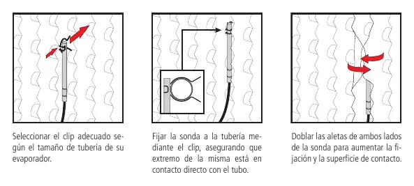
- Probes must be installed correctly to ensure accurate readings and efficient system operation.
- The AKO-16525AN model must never be operated without its internal antenna.
Wiring
Always disconnect the power supply before performing any wiring. Probes and their cables must never be installed in the same conduit as power, control, or supply cables. The power supply circuit must include a switch of at least 2 A, 230 V, located near the device. Relay output cables must have a cross-section of 2.5 mm² and be rated for temperatures of 70 °C or higher.
Configuration and Operation
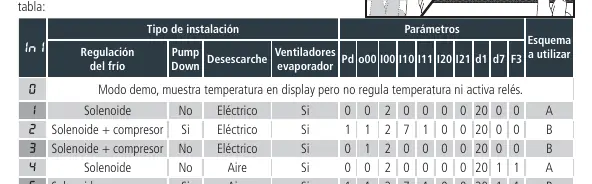
Upon first power-up, the unit enters the Assistant mode. Follow the steps to select the installation type (InI option) and set the desired Set Point. The controller offers both a condensed and an extended programming menu for advanced parameter adjustments. The SELFDRIVE mode is active by default, automatically managing defrosts and fan operation based on system conditions.
Maintenance and Troubleshooting
Clean the unit surface with a soft cloth, water, and soap. Avoid abrasive detergents, alcohol, or solvents. If an error occurs, the display will show a specific code. Common errors include probe failures (E1/E2/E3) or system instability during calibration (E12/E22). Refer to the troubleshooting section for specific solutions, such as checking probe connections or ensuring the cold room door remains closed during calibration.
Technical Specifications
The controller operates on 100-240 V~ 50/60 Hz. It features multiple programmable relay outputs (AUX1, AUX2, DEF, COOL, FAN) with a maximum nominal current of 15 A. The operating temperature range is -50.0 °C to 99.9 °C, with a resolution of 0.1 °C.
Related manuals
Related manuals from the same brand or category.
General / Other Manuals
AKO-16526A / AKO-16526AN Advanced Temperature Controller
AKOGeneral / Other Manuals
AKO 16526A V2 Advanced Temperature Controller
AKOGeneral / Other Manuals
AKO-15724/AKO-15725 Temperature Data Logger
AKO
Manual page author
Michael Turner
Technical manual editor
Reviews PDF manuals for structure, safety notes, and practical product details so readers can find the right information quickly.