Electronics / Radio Antennas
Alpha Antenna HexTenna Yagi User Manual
Quick guide for the Alpha Antenna HexTenna Yagi. Includes deployment instructions, element length charts for 20M-2M bands, environmental operating parameters, and tuning tips for optimal SWR.
Quick answers from the manual
Quick answer
- The HexTenna Yagi is a portable VHF/HF antenna. Deployment involves mounting the boom on a mast, adjusting telescopic elements to specific lengths based on the band, and tuning for the lowest SWR. p. 1
Key actions
- Adjust driven elements to the lengths specified in the chart for the desired band. p. 1
- Set reflector length to 4% longer than driven elements, or retract 4% to use as a director. p. 1
Problems and fixes
High SWR
Install a 1:1 balun at the feed point and adjust element lengths.
p. 1Technical specifications
| Parameter | Value | Meaning | Pages |
|---|---|---|---|
| Maximum Power | 1.5KW PEP SSB | Power handling limit | p. 1 |
Where to find it in the PDF
- Deployment Instructions and Element Lengths p. 1
- Antenna Diagram p. 2
Table of contents
Quick guide from the manual
The HexTenna Yagi is a portable VHF/HF antenna system designed for deployment on a tripod or mast. The system requires manual adjustment of telescopic elements to achieve the lowest SWR for specific bands. Proper tuning involves adjusting driven elements and setting reflectors or directors based on the desired pattern.
Environmental operating parameters
To ensure safe operation and longevity of the antenna, observe the following environmental limits:
- Temperature range: -15 to 130 degrees Fahrenheit.
- Wind limit: Up to 50 Mph (when appropriately guyed).
Instructions for deployment
- Set up your mounting option, such as a tripod with a mast or a simple mast.
- Adjust the driven elements to the suggested length by pulling on the tips of the telescopic whips.
- Pull the tip of the reflector whips out and add 4% more length than the driven elements. To use these elements as a director, retract them by 4%. Adjust based on the desired pattern and lowest SWR.
- Install the boom with the built-in mount onto your mast.
- Screw the four adjusted elements into their respective hubs.
- Guy the system based on environmental conditions, then attach your feedline.
- Adjust the elements for the lowest SWR if necessary.
Driven element lengths
Actual length is impacted by ground conditions and height. When tuning for lower SWR, add 4%-10% for the reflector on 2-17M, or detract 4%-10% if used as a director on 2-20M.
- 20 Meters: 16 feet 11 1/2 inches
- 17 Meters: 13 feet 3/4 inches
- 15 Meters: 10 feet 11 1/2 inches
- 12 Meters: 9 feet 6 inches
- 10 Meters: 8 feet 3 1/2 inches
- 6 Meters: 4 feet 8 inches
- 2 Meters: 4 feet 7 1/2 inches
Pro-tips for tuning
- When driven elements are longer, the two elements that are not driven act as directors.
- A 1:1 balun (available option) installed at the antenna feed point manages common mode current and will lower SWR.
- Reflector elements often need to be 8-10% longer than a driven element to achieve lower SWR, especially without a balun.
- If you cannot get 20M to tune, check your element lengths and ensure a 1:1 balun is used.
- Gain is directed opposite the reflector on 17-2M (or 20M if a balun is used), or in the direction of the director for 20M-2M.
Practical help
Common problems
High SWR
Adjust element lengths according to the chart. Ensure a 1:1 balun is installed at the feed point to manage common mode current.
20M band not tuning
Verify element lengths and ensure a 1:1 balun is being used.
Before use
- Tripod or mast for mounting
- Measuring tool to set telescopic element lengths
- Guy wires for high wind conditions
Specs in practice
- Maximum Power
- 1.5KW PEP SSB
- Operating Temperature
- -15 to 130 degrees Fahrenheit
- Wind Tolerance
- Up to 50 Mph when appropriately guyed
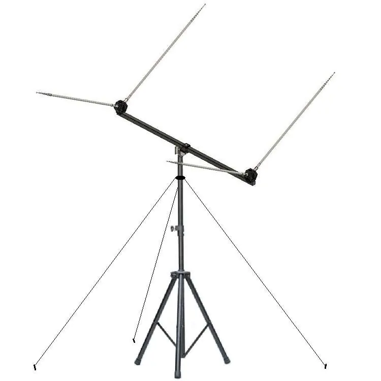
Images and diagrams
- The antenna is mounted on a tripod with a central mast.
- The boom holds the telescopic elements which must be adjusted to specific lengths.
Model compatibility
- Compatible with 2 through 20 meter bands.
- Optional 1:1 balun recommended for better SWR management.

Manual page author
Emily Carter
User documentation editor
Prepares concise manual descriptions and highlights the most useful setup, operation, and maintenance information for readers.