Electronics / Radio Antennas
Alpha Antenna VHF UHF HF EmComm Loop Antenna
Quick setup and tuning guide for the Alpha Antenna VHF UHF HF EmComm Loop. Includes assembly steps, tuning instructions for HF/VHF/UHF, and technical specifications.
Table of contents
Quick guide from the manual
The Alpha Antenna VHF UHF HF EmComm Loop is a portable antenna designed for POTA, SOTA, home, or portable use. Before operating, ensure your radio is set to the lowest power setting while tuning and properly adjust the Mic Gain for SSB/AM/FM modes.
Assembly
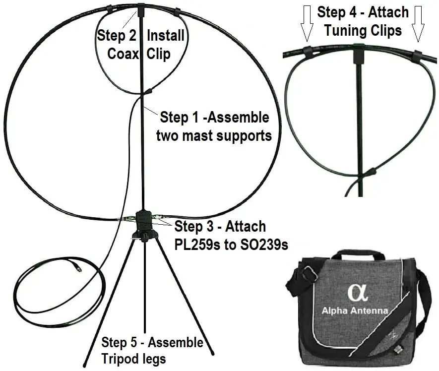
- Assemble mast supports: Connect the two mast supports and insert the center mast into the top hole on the tuning box.
- Attach coax clip: Place the top center coax clip at the top of the mast.
- Connect loop: Screw the PL259 connectors on the outer large loop onto the SO239 connectors on the tuning box.
- Install tuning clips: Ensure the two tuning clips are installed on the inner/outer loops.
- Mounting: Install on a tripod with a 1/4-20 thread or insert the included tripod legs into the bottom holes on the tuning box.
Tuning Instructions
HF Tuning: Turn the tuning knob first, then adjust the two tuning clips (in/out) at the top of the loop to achieve the lowest SWR. Repeat as necessary. A tuning rod is included and can be stored in the housing or inserted into the knob to facilitate easier tuning.
VHF/UHF Tuning: Adjust the two tuning clips (in/out) to achieve the lowest SWR.
Specifications
Operating Parameters:
- Max Power: 100W PEP SSB, 50W CW, 25W Digital
- Frequency Coverage: 7MHz to 21.450MHz, plus 2 Meters and 440MHz
- Impedance: 50 ohms
Usage and Physical Parameters:
- Directionality: Semi-Directional
- Purpose: NVIS & DX
- IP Rating: IP-53
- Weight: 24 Ounces (0.68Kg)
Support
If you have any questions regarding the operation or setup of your antenna, please email [email protected].
Practical help
Common problems
High SWR during tuning
Ensure the tuning knob is adjusted first (for HF), then fine-tune by moving the two tuning clips (in/out) at the top of the loop.
Distorted audio or signal issues
Properly adjust the Mic Gain on your radio before using SSB/AM/FM modes.
Before use
- Set radio to the lowest power setting while tuning
- Adjust Mic Gain settings
- Assemble mast supports and insert into tuning box
- Attach coax clip to the top of the mast
- Secure PL259 connectors to SO239 ports
- Install tuning clips on the loops
Specs in practice
- Frequency Coverage
- Covers 7MHz to 21.450MHz, plus 2 Meters and 440MHz bands.
Images and diagrams
- The assembly diagram illustrates the 5-step process: assembling mast supports, installing the coax clip, connecting PL259 to SO239, attaching tuning clips, and assembling tripod legs.
Model compatibility
- Designed for NVIS (Near Vertical Incidence Skywave) and DX communication.
- Compatible with tripods using a 1/4-20 thread.

Manual page author
Michael Turner
Technical manual editor
Reviews PDF manuals for structure, safety notes, and practical product details so readers can find the right information quickly.