Power / Uninterruptible Power Supplies
Operation Manual for APC Smart-UPS C 1000/1500 VA Tower
Quick guide for the APC Smart-UPS C 1000/1500 VA Tower. Learn about operation, sensitivity settings, status indicators, troubleshooting, and maintenance.
Table of contents
Manual images
Click an image to enlargeImportant Information
The APC Smart-UPS C 1000/1500 VA Tower is a high-performance uninterruptible power supply (UPS) designed to protect electronic equipment from power disturbances. Before installing, read the included Safety Guide. This unit is for indoor use only. Ensure adequate ventilation and do not block air vents. Connect the UPS directly to a wall outlet; do not use surge protectors or extension cords. The battery typically lasts two to five years, depending on environmental factors.
Product Overview
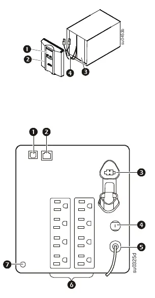
The front panel features a display interface, bezel, battery, and internal battery connector. The rear panel includes a USB port, serial data port, battery connector, circuit breaker, UPS input, outlets, and a ground screw.
Operation and Setup
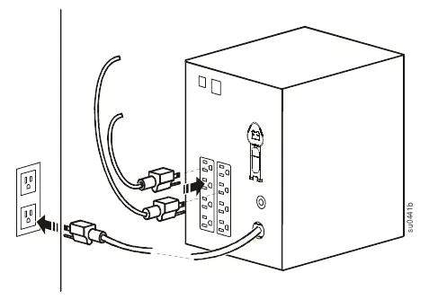
To connect equipment, plug devices into the UPS outlets. Connect the UPS to a two-pole, three-wire, grounded utility power source. Note that the UPS will charge to 90% capacity in the first three hours of normal operation; do not expect full battery runtime during this initial period. Use the USB or serial port to connect to a computer for power management software.
LCD and Sensitivity Settings
The display interface can be configured for continuous illumination or power-saving mode. To adjust, press and hold the DISPLAY button for two seconds. You can also adjust the transfer voltage sensitivity to protect connected equipment from line voltage distortions. To enter Program mode, connect the UPS to utility power (turned off), then press and hold the POWER button for six seconds until the load capacity bar flashes. Use the POWER button to scroll through Low, Medium, and High sensitivity levels.
Status Indicators
The front panel provides visual and audible feedback. Key indicators include:
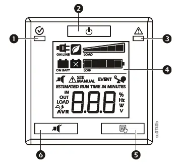
- On Line: UPS is supplying conditioned utility power.
- Green Mode: UPS is operating at maximum efficiency.
- Load Capacity: Each bar represents 20% of load.
- Battery Charge: Each bar represents 20% of charge.
- Overload: Connected equipment is drawing too much power.
- AVR: UPS is compensating for low input voltage.
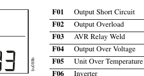
- System Faults: Internal fault occurred; check the fault number on the display.
Troubleshooting
If the UPS does not turn on, check the power cable connection, the input circuit breaker, or the battery connector. If the UPS is operating on battery while connected to utility power, check the input voltage or reduce sensitivity. If the replace battery icon is illuminated, allow the battery to recharge for at least four hours and perform a self-test. If the Site Wiring LED is flashing, have a qualified electrician inspect the building wiring.
Service and Warranty
If the unit requires service, do not return it to the dealer. Review the troubleshooting section first. If the problem persists, contact APC Customer Support via www.apc.com. When shipping the unit, always disconnect the internal battery. The product comes with a two-year factory warranty covering defects in materials and workmanship.
Official resources from the manual
Practical help
Common problems
UPS will not turn on
Check power cable connection, reset the input circuit breaker, or ensure battery connections are secure.
UPS operating on battery while connected to utility power
Move to a different outlet, test input voltage, or reduce UPS sensitivity.
Replace battery icon illuminated
Allow battery to recharge for at least four hours and perform a self-test; replace if the problem persists.
Site Wiring LED flashing
Have a qualified electrician inspect the building wiring for missing ground, hot-neutral, or polarity reversal.
Before use
- Read the Safety Guide included in the package.
- Ensure the unit is placed in a well-ventilated area.
- Connect directly to a wall outlet (do not use surge protectors).
- Charge the battery for at least 3 hours to reach 90% capacity.
- Verify the UPS is connected to a two-pole, three-wire, grounded source.
Specs in practice
- Operating Temperature
- 0° to 40° C (32° to 104° F).
- Operating Elevation
- Up to 3,000 m (10,000 ft).
Images and diagrams
- Front panel: Display interface, Bezel, Battery, Internal battery connector.
- Rear panel: USB Port, Serial data port, Battery connector, Circuit breaker, UPS input, Outlets, Ground screw.
Model compatibility
- Intended for indoor use only.
- Connect to a two-pole, three-wire, grounded source only.

Manual page author
Emily Carter
User documentation editor
Prepares concise manual descriptions and highlights the most useful setup, operation, and maintenance information for readers.