Lighting / Fixtures
User Manual for Artemide Stellar Nebula Pendant Light
Quick guide for the Artemide Stellar Nebula pendant light. Includes installation steps, wiring diagrams for 120V and 0-10V dimming, and maintenance instructions.
Table of contents
Manual images
Click an image to enlargeQuick guide from the manual
This document provides essential installation and wiring instructions for the Artemide Stellar Nebula pendant light. Please ensure that installation is performed by qualified personnel and that two people are available for the assembly process to ensure safety.
Installation
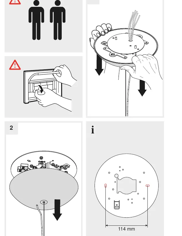
- Preparation: Ensure the ceiling structure can support the fixture. The mounting hole spacing is 114 mm.
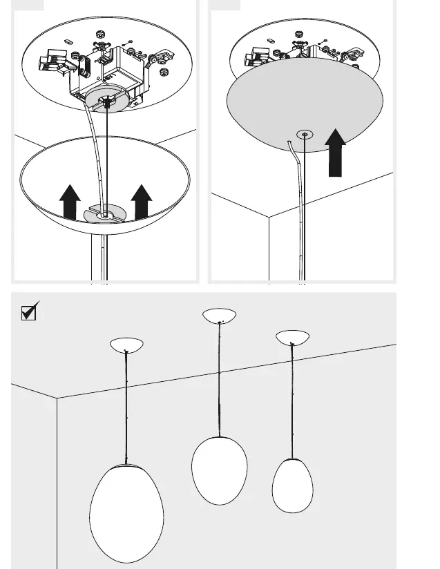
- Mounting: Attach the mounting plate to the ceiling.
- Assembly: Secure the fixture body to the mounting plate.
- Finalizing: Complete the assembly by attaching the shade to the fixture body.
Wiring
The fixture supports two different wiring configurations depending on your electrical system:
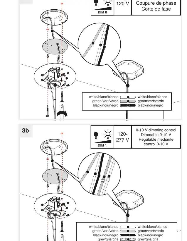
- 120 V (Phase cut): Connect the white, green, and black wires according to the diagram labeled 3a.
- 120-277 V (0-10 V dimming): Connect the white, green, black, grey, and purple wires according to the diagram labeled 3b.
Maintenance
To clean the fixture, use only water. Do not use detergents, chemical cleaners, or abrasive materials, as these may damage the surface of the lamp.
Contact
For support, contact Artemide at their respective locations in Italy, the USA, or Canada. Visit www.artemide.com or www.artemide.net for more information.
Official resources from the manual
Manufacturer information
Artemide S.p.A.
Practical help
Common problems
Fixture not dimming correctly
Verify that the wiring matches the specific dimming control type (Phase cut for 120V or 0-10V for 120-277V).
Before use
- Ensure two people are available for installation
- Verify the electrical system voltage (120V or 120-277V)
- Check that the mounting surface is suitable for the fixture weight
- Confirm the 114 mm mounting hole spacing
Specs in practice
- 0-10 V dimming
- Dimming method compatible with 120-277V systems
Images and diagrams
- Diagram 3a shows wiring for 120V phase cut dimming
- Diagram 3b shows wiring for 120-277V 0-10V dimming
Model compatibility
- Requires specific dimming control hardware based on the voltage configuration

Manual page author
David Miller
Documentation analyst
Organizes user manual content into clear summaries, with attention to model details, product context, and everyday usability.