HVAC / Air Conditioners
Installation Instructions for Bryant 114S, 115S Air Conditioner
Professional installation guide for Bryant 114S and 115S Legacy™ Line Air Conditioners. Includes safety protocols, piping connection steps, electrical wiring diagrams, charging procedures, and start-up requirements.
Table of contents
Quick Guide for Installation
This document provides installation instructions for the Bryant 114S and 115S Legacy™ Line Air Conditioners. Installation must be performed by EPA-qualified personnel. Key steps include mounting the unit on a level pad, connecting refrigerant piping, performing a deep vacuum, making electrical connections, and charging the system based on the metering device (TXV or piston).
Safety Considerations
Improper installation can lead to fire, electrical shock, or explosion. Always follow these safety guidelines:
- Electrical Shock: Ensure the main electrical disconnect switch is in the OFF position before servicing.
- Explosion Hazard: Never use air or oxygen for leak testing. Use nitrogen.
- Fire Hazard: Ensure refrigerant charge is removed before brazing. Use a quenching cloth.
- Personal Protective Equipment: Wear safety glasses, protective clothing, and work gloves.
Installation and Mounting
The unit must be installed in a location no higher than 10,000 feet (3000 meters) above sea level. Ensure the unit is placed away from areas where operation sound may disturb the customer.
- Clearance: Maintain 24 inches (610 mm) of clearance to the service end and 48 inches (1219 mm) above the unit. For proper airflow, maintain 6 inches (152 mm) on one side and 12 inches (305 mm) on all other sides.
- Mounting: Install on a solid, level mounting pad. If required by local codes, use tie-down bolts through the base pan knockouts.
- Rooftop Applications: Mount on a level platform or frame above a load-bearing wall.
Piping Connections
Use refrigeration-grade tubing. Rated diameters are recommended for lines up to 80 feet (24 m).
- Sweat Connections: Clean tube ends with emery cloth. Wrap service valves with a wet cloth to prevent heat damage while brazing.
- Filter Drier: Installation of the factory-supplied liquid-line filter drier is mandatory. Ensure the flow arrow points toward the indoor coil.
- Evacuation: Use the deep vacuum method to pull a vacuum of 500 microns. A tight system will hold 1000 microns after approximately 7 minutes.
Electrical Connections
Ensure field wiring complies with local and national codes. Use copper wire only between the disconnect switch and the unit.
- Grounding: Connect the ground wire to the ground connection in the control box.
- Power Wiring: Connect power wiring to the contactor.
- Control Wiring: Use 18 AWG color-coded, insulated wire. If the thermostat is more than 100 feet (30 m) away, use 16 AWG wire.
- 3-Phase Monitor: For 3-phase units, a monitor is factory-installed. If the LED flashes, disconnect power and interchange two field-wiring leads.
Start-Up and Charging
Follow these steps to start the system:
- After evacuation, fully open liquid and vapor service valves.
- Replace stem caps and tighten.
- Energize the system and set the thermostat to COOL.
- Operate for 15 minutes before checking the charge.
Charging Methods:
- TXV Systems: Use the subcooling method.
- Piston Systems: Use the superheat method.
Refer to the rating plate and the provided tables in the manual for specific subcooling or superheat targets based on outdoor and indoor temperatures.
Maintenance
Periodic maintenance is required for high performance. Frequency may vary based on geographic location, such as coastal areas. Always refer to the Owner's Manual for specific maintenance schedules.
Practical help
Common problems
3-Phase Monitor LED flashing
Indicates reversed phase. Disconnect power and interchange 2 field-wiring leads on the unit contactor.
System noise in living area
Often caused by gas pulsations from improper installation. Ensure proper tubing installation and isolation.
Refrigerant leaks
Do not use air or oxygen for leak testing. Use nitrogen. Ensure all joints are properly brazed.
Before use
- Ensure installation is performed by EPA-qualified personnel.
- Verify unit is level within ±2°.
- Check that refrigerant tube diameters are appropriate for unit capacity.
- Ensure all electrical disconnects are in the OFF position before servicing.
- Verify the factory-supplied liquid-line filter drier is installed.
- Ensure the system is evacuated to 500 microns.
Show more Show less
Specs in practice
- Subcooling Method
- Charging procedure required for units equipped with a TXV.
- Superheat Method
- Charging procedure required for units equipped with indoor pistons.
- Operating Ambient
- Minimum outdoor operating temperature in cooling mode is 55°F (13°C).
Images and diagrams
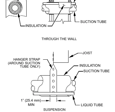
- Fig 1: Piping Installation - Shows proper wall penetration, suspension, and insulation of refrigerant tubes.
- Fig 6: Line Connections - Illustrates power wiring to the contactor and ground connection.
- Fig 7: Wiring Diagrams - Shows connections between thermostat, furnace/fan coil, and air conditioner.
- Fig 8: 3-Phase Monitor Control - Shows the LED indicator and wiring terminals for 3-phase units.
Model compatibility
- 114S/115S units are designed for split system applications.
- Requires factory-approved indoor units.
- 3-phase monitor applies to 3-phase units only.

Manual page author
Emily Carter
User documentation editor