HVAC / Air Conditioners
Installation Instructions for Bryant 105A, 106A, 113A, 114C, 116B Air Conditioners
Comprehensive installation guide for Bryant Legacy Line single-stage air conditioners. Includes detailed procedures for mounting, refrigerant piping, electrical wiring, system charging, and accessory setup.
Quick answers from the manual
Quick answer
- This manual provides installation, piping, electrical connection, and system charging instructions for Bryant 105A, 106A, 113A, 114C, and 116B air conditioners. p. 1, 2, 3, 4
Key actions
- Install unit on a solid, level mounting pad. p. 2
- Connect refrigerant tubing. p. 3
- Evacuate system to 500 microns. p. 3, 4
- Make electrical connections. p. 6
- Check refrigerant charge. p. 4, 7
First start
- Open service valves. p. 7
- Energize system. p. 7
- Set thermostat to COOL. p. 7
- Operate for 15 minutes. p. 7
Show 4 more answers Show less
Problems and fixes
Noise in living area
Locate unit away from windows/decks, ensure proper tube diameters, avoid unnecessary bends, and isolate tubing from structure.
p. 1
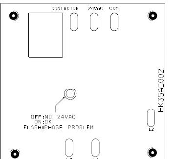
3-Phase Monitor LED flashing
Disconnect power to unit and interchange 2 field-wiring leads on unit contactor.
p. 7Error codes
| Code | Meaning | Action | Pages |
|---|---|---|---|
| LED FLASHING | Reversed phase | Disconnect power to unit and interchange 2 field-wiring leads on unit contactor. | p. 7 |
Technical specifications
| Parameter | Value | Meaning | Pages |
|---|---|---|---|
| Operating Ambient (Cooling) | 55°F to 125°F (non-13 SEER) or 115°F (13 SEER) | Allowable outdoor temperature range for cooling mode | p. 2 |
| Max Liquid-line size | 3/8-in. OD | Maximum size for residential applications | p. 2 |
| Vacuum requirement | 500 microns | Required vacuum depth for system evacuation | p. 3, 4 |
Where to find it in the PDF
- Safety and General Installation p. 1
- Installation and Clearance p. 2
- Piping and Evacuation p. 3
- Charging Methods p. 4
- Charging Tables p. 5
- Electrical Connections p. 6
- Start-Up and 3-Phase Monitor p. 7
- Refrigerant Charge Tables p. 8
Table of contents
Manual images
Click an image to enlargeQuick Guide for Installation
This document provides installation instructions for Bryant Legacy Line single-stage air conditioners. Before starting, ensure you have read the entire manual. Key safety requirements include wearing protective gear, using a fire extinguisher during brazing, and ensuring the main electrical disconnect is in the OFF position before servicing. Never use oxygen for leak testing.
Installation and Mounting
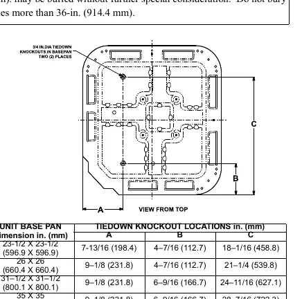
Select a location for the unit away from windows, patios, or decks to minimize noise. The unit must be installed on a solid, level mounting pad. If local codes require, use tie-down bolts through the base pan knockouts. For rooftop applications, mount on a level platform above a load-bearing wall and isolate the unit from the structure to minimize vibration.
Clearance Requirements
- Service end: 24 inches (609.6 mm)
- Above unit: 48 inches (1219.2 mm)
- One side: 6 inches (152.4 mm)
- Remaining sides: 12 inches (304.8 mm)
- Between units: 24 inches (609.6 mm) or 18 inches (457.2 mm) if no overhang within 12 feet.
Refrigerant Piping and Connections
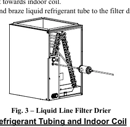
Use refrigerant-grade tubing. Keep lines as direct as possible and avoid contact with water pipes, ductwork, or wall studs. Seal wall penetrations with RTV or pliable caulk. A factory-supplied liquid-line filter drier must be installed in the liquid line. After connecting, the system must be evacuated to 500 microns to remove moisture and contamination.
Electrical Connections
Ensure field wiring complies with local and national electrical codes. Use copper wire only. The disconnect switch must be within sight of the unit. Route 24V control wires through the grommet and connect to the thermostat. For 3-phase units, a monitor is factory-installed; if the LED flashes, interchange two field-wiring leads on the contactor.
System Charging Procedures
The unit must operate for at least 15 minutes before checking the charge. Favorable conditions for charging are outdoor temperatures between 70°F and 100°F (21°C - 38°C) and indoor temperatures between 70°F and 80°F (21°C - 27°C).
Charging Methods
- Units with TXV: Use the subcooling method. Refer to the rating plate for required subcooling temperature.
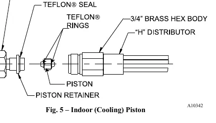
- Units with Indoor Piston: Use the superheat method. Refer to the provided superheat charging tables based on outdoor temperature and indoor wet-bulb temperature.
Start-Up and Maintenance
After installation, perform a final check: ensure wiring is routed away from sharp edges, service valve caps are tightened to 1/12-turn past finger tight, and all panels are secure. Periodic maintenance is required for continued performance; refer to the Owner's Manual for specific schedules.
Practical help
Common problems
Noise in living area
Ensure the unit is located away from windows/decks and that refrigerant tubing does not contact water pipes, ductwork, or wall studs.
3-Phase monitor LED flashing
Indicates a reversed phase. Disconnect power and interchange two field-wiring leads on the unit contactor.
System not cooling properly
Check refrigerant charge using the subcooling or superheat method after the unit has operated for at least 15 minutes.
Before use
- Verify unit is level on a solid mounting pad.
- Ensure refrigerant tubing is not in direct contact with structure components.
- Install the factory-supplied liquid-line filter drier.
- Evacuate the system to 500 microns.
- Confirm electrical disconnect is within sight of the unit.
- Check that service valve caps are tightened.
Show more Show less
Images and diagrams
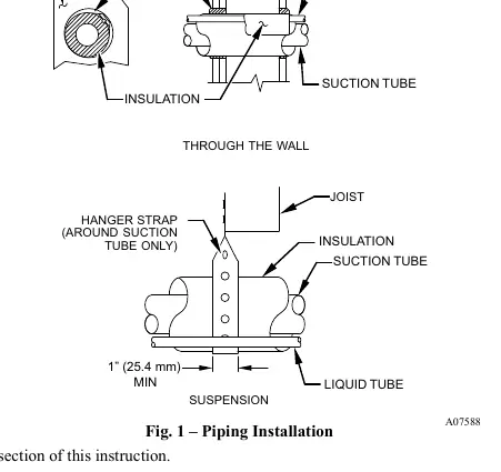
- Fig 1: Shows proper hanger strap placement and wall sealing for refrigerant tubing.
- Fig 2: Provides dimensions for base pan mounting and tie-down knockout locations.
- Fig 6: Illustrates the correct wiring of the contactor and ground connections.
- Fig 7: Explains the LED status codes for the 3-phase monitor.
Model compatibility
- Compatible with factory-approved AHRI rated indoor units.
- Requires specific accessory kits for low-ambient cooling or long line applications.
- Not for use with capillary tubes.

Manual page author
Michael Turner
Technical manual editor