HVAC / Heat Pumps
Installation Instructions for Bryant 215S Single Stage Heat Pump
A comprehensive installation guide for the Bryant 215S Single Stage Heat Pump. This manual covers safety considerations, mounting, refrigerant piping, electrical connections, system start-up, charging procedures, and defrost control...
Quick answers from the manual
Quick answer
- This manual provides installation, wiring, and charging instructions for the Bryant 215S Single Stage Heat Pump. It covers mounting, piping, electrical connections, and system start-up. p. 1, 6
Key actions
- Mounting the unit p. 2
- Connecting refrigerant lines p. 3, 4
- Electrical wiring p. 5, 6
- Charging the system p. 8
First start
- Ensure system is evacuated, open service valves, set thermostat, and operate for 15 minutes before checking charge. p. 6, 8
Show 4 more answers Show less
Problems and fixes
3-Phase Monitor LED flashing
Reversed phase detected.
p. 5Maintenance and reset
- Forcing a defrost will reset the defrost interval to the DIP switch setting. p. 7
Technical specifications
| Parameter | Value | Meaning | Pages |
|---|---|---|---|
| Maximum liquid-line size | 3/8-in. OD | For all residential applications | p. 1 |
Where to find it in the PDF
- Installation Instructions p. 1, 2
- Piping Connections p. 3, 4
- Electrical Connections p. 5, 6
- Defrost Control p. 7
- Charging Charts p. 8, 9, 10
Table of contents
Manual images
Click an image to enlargeQuick guide from the manual
This document provides essential installation and setup procedures for the Bryant 215S Single Stage Heat Pump. Before beginning, ensure all safety codes are followed, including wearing protective gear. The unit must be installed by a qualified professional. Key steps include proper unit location, secure mounting, correct refrigerant piping, and accurate electrical wiring. Always verify the system charge using the subcooling or superheat methods as specified in the manual.
Installation Recommendations
Proper installation is critical to prevent noise and ensure efficiency:
- Locate the unit away from windows, patios, and decks to minimize noise disturbance.
- Ensure vapor and liquid tube diameters are appropriate for the unit capacity.
- Run refrigerant tubes as directly as possible, avoiding unnecessary turns.
- Leave slack in tubing to absorb vibration and avoid contact with water pipes or ductwork.
- Use hanger straps that are 1 inch wide and conform to the shape of the tubing insulation.
Mounting and Clearance
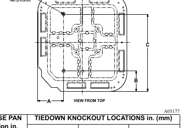
The unit must be installed on a solid, level mounting pad. If local codes require, use tie-down bolts through the base pan knockouts. For rooftop applications, mount on a level platform above a load-bearing wall. Maintain the following clearances for proper airflow and service:
- Service end: 24 inches.
- Above unit: 48 inches.
- Sides: 6 inches on one side, 12 inches on all remaining sides.
- Between units: 24 inches (or 18 inches if no overhang within 12 feet).
Piping Connections
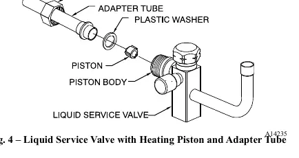
Outdoor units are shipped with a refrigerant charge sealed in the unit. Keep service valves closed until all piping work is complete. When brazing, wrap service valves with a wet cloth to prevent heat damage. Use refrigerant-grade tubing and ensure the system is evacuated to 500 microns before opening service valves.
Electrical Connections
Ensure field wiring complies with local and national electrical codes. Use copper wire only between the disconnect switch and the unit. Route control wires through the grommet and connect to the control wiring. For 3-phase units, a monitor control is provided to indicate phase status.
Start-Up and Charging
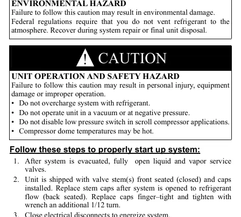
After evacuation, open the liquid and vapor service valves. Set the thermostat to the desired temperature and operate the unit for at least 15 minutes before checking the charge. Use the subcooling method for units with a TXV and the superheat method for units with indoor pistons. Refer to the provided tables in the manual for specific temperature and pressure values.
Defrost Control
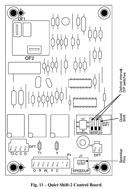
The unit features a time/temperature defrost control. The 'Quiet Shift-2' mode is a field-selectable option (factory set to OFF) that reduces noise during defrost cycle transitions. It can be enabled by setting DIP switch 3 on the defrost board to the ON position.
Practical help
Common problems
Noise in living area
Ensure unit is located away from windows/decks and tubing is isolated from structure.
Improper charge
Use subcooling method for TXV or superheat method for piston systems as described in the manual.
Defrost cycle noise
Enable 'Quiet Shift-2' by setting DIP switch 3 on the defrost board to the ON position.
3-Phase Monitor LED flashing
Indicates reversed phase. Check power supply wiring.
Before use
- Verify unit is level within ±2°
- Check clearance requirements (24 in. service end, 48 in. above)
- Ensure refrigerant tubing is clean and properly sized
- Confirm electrical voltage matches rating plate
- Ensure factory-supplied liquid-line filter drier is installed
Show more Show less
Specs in practice
- Quiet Shift-2
- Defrost mode that reduces noise during cycle transitions.
Images and diagrams
- Fig 1: Shows proper tubing installation through walls and suspension.
- Fig 2: Details tiedown knockout locations on the base pan.
- Fig 8: Illustrates line connections to the contactor.
- Fig 11: Shows the Quiet Shift-2 control board and DIP switch settings.
Model compatibility
- Maximum liquid-line size is 3/8-in. OD for all residential applications.
- Do not use soft solder (materials melting below 800°F/427°C) for brazing.
- Units with louver panels require 24 inches between units.

Manual page author
Emily Carter
User documentation editor