HVAC / Air Conditioners
Installation Guide for Bryant 146SAN Air Conditioner
Comprehensive installation guide for the Bryant 146SAN Preferred Series Air Conditioner. Includes detailed instructions for mounting, refrigerant piping, electrical connections, system start-up, and charging procedures.
Table of contents
Manual images
Click an image to enlargeQuick guide from the manual
This document provides installation instructions for the Bryant 146SAN Preferred Series Air Conditioner. Important: This appliance must only be installed by EPA-qualified personnel. The unit is designed for use with R-454B indoor units only. Always follow local building codes and the National Electrical Code (NEC).
Installation and Mounting
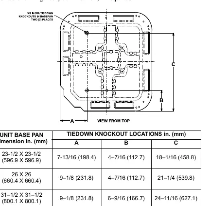
The unit must be installed on a solid, level mounting pad. If local codes require, use tie-down bolts through the base pan knockouts. Ensure the unit is level within ±2° (±3/8 in./ft.).

Clearance Requirements
- Service end: 24 in. (610 mm) clearance.
- Above unit: 48 in. (1219 mm) clearance.
- Sides: 6 in. (152 mm) on one side, 12 in. (305 mm) on all remaining sides.
- Between units: 24 in. (610 mm) or 18 in. (457 mm) if no overhang within 12 ft.
Piping Connections
Outdoor units may be connected using accessory tubing or field-supplied refrigerant-grade tubing. Rated diameters are recommended up to 80 ft. (24 m).
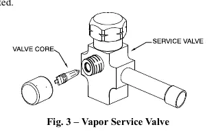
- Brazing: Use a properly sized swedge tool. Wrap service valves with a wet cloth to act as a heat sink. Do not use soft solder.
- Filter Drier: Installation of the factory-supplied liquid-line filter drier is required.
- Evacuation: Evacuate the system to 500 microns using a vacuum pump.
- Leak Check: Pressure test with nitrogen to approximately 200 psi. The system must hold pressure for 1 hour.
Electrical Connections
Ensure voltage is within limits shown on the unit rating plate. Use copper wire only between the disconnect switch and the unit.
- Grounding: The unit must have an uninterrupted ground connection.
- Control Wiring: Use No. 18 AWG color-coded, insulated wire. If the thermostat is more than 100 ft. (30 m) away, use No. 16 AWG wire.
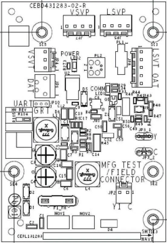
- InteliSense Technology: This unit is compatible with Ecobee for Bryant smart thermostats. The control board includes sensors for pressure and temperature monitoring.
System Start-Up and Charging
The unit is factory-charged for 15 ft. (4.6 m) of lineset. Adjust charge by adding or removing 0.6 oz/ft of 3/8 liquid line.
- Open liquid and vapor service valves.
- Set thermostat to desired temperature and operate for 15 minutes.
- Use the subcooling method for charging. Measure liquid service valve pressure and liquid line temperature.
- Refer to the provided subcooling table (Table 3) to determine the required temperature based on pressure.
Maintenance
Periodic maintenance is required for high performance. Frequency depends on geographic location, such as coastal areas. Refer to the Owner's Manual for specific maintenance schedules.
Practical help
Common problems
Noise in living area
Often caused by gas pulsations from improper installation. Ensure refrigerant tubes are isolated from structure.
System not cooling
Check refrigerant charge using the subcooling method and verify thermostat settings.
Electrical fault
Ensure the unit cabinet has an uninterrupted ground connection.
Before use
- Verify installer is EPA qualified.
- Ensure unit is level within ±2°.
- Check that refrigerant tubing is not in contact with water pipes or ductwork.
- Confirm electrical disconnect is in the OFF position during installation.
- Ensure filter drier is installed in the liquid line.
- Verify system is evacuated to 500 microns.
Show more Show less
Images and diagrams
- Fig 1: Illustrates proper tubing installation through walls and hanger strap usage.
- Fig 2: Details tiedown knockout locations for mounting pads.
- Fig 3: Shows vapor service valve components.
- Fig 6: Wiring diagram for line connections.
- Fig 8: Layout of the InteliSense control board.
Model compatibility
- For use with R-454B indoor units only.
- InteliSense technology requires Ecobee for Bryant smart thermostat.

Manual page author
Emily Carter
User documentation editor