HVAC / Air Conditioners
Installation Guide for Bryant 124ANS Air Conditioner
Comprehensive installation and maintenance guide for the Bryant 124ANS Preferred Series Air Conditioner. Includes wiring diagrams, refrigerant piping instructions, and safety procedures.
Table of contents
Manual images
Click an image to enlargeQuick Guide from the Manual
This document provides installation and service instructions for the Bryant 124ANS Preferred Series Air Conditioner. Before starting, ensure you have read the entire manual. Key requirements include proper clearance for airflow, correct refrigerant piping practices, and adherence to local electrical codes. Always use factory-authorized kits for modifications.
Safety Considerations
Improper installation or service can cause explosion, fire, or electrical shock. Always wear safety glasses, protective clothing, and work gloves. Ensure the main electrical disconnect switch is in the OFF position and locked out before servicing. Use a fire extinguisher during brazing operations.
Installation
Clearance Requirements: Ensure adequate space for airflow and service. For single units, allow at least 6 inches on the coil side and 20 inches on the fan side. Allow 24 inches on the compressor end for service. Multi-unit applications require 24 inches between units.
Mounting: The unit can be mounted on a solid, level concrete pad on the ground or on a level platform at least 6 inches above a roof surface. If mounting on the ground, ensure water or ice from the roof does not fall on the unit.
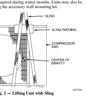
Rigging: Keep the unit upright and use a sling with spreader bars to prevent damage. Ensure all panels are securely in place before rigging.
Refrigerant Piping
Use refrigerant-grade tubing. Do not use less than 10 feet of interconnecting tubing. If any section of pipe is buried, a 6-inch vertical rise to the valve connections is required. When brazing, pass nitrogen or inert gas through the piping to prevent copper oxide formation. Always wrap service valves with a wet cloth or heat sink material to prevent damage.
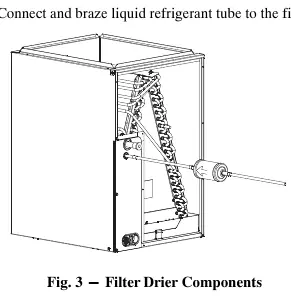
Filter Drier: Install the factory-specified liquid-line filter drier. Replace it whenever the refrigeration system is exposed to the atmosphere.
Electrical Connections
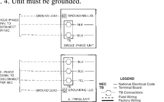
Power Wiring: Provide a fused disconnect switch within sight of the unit. Use copper wire only, with a minimum rating of 75°C. The unit must be grounded in accordance with NEC and local codes.
Control Circuit Wiring: Control voltage is 24V (40VA minimum). Use No. 18 AWG color-coded wire for distances up to 100 feet; use No. 16 AWG for longer runs to avoid voltage drop.
Start-Up Procedures
Preliminary Checks: Verify all wiring connections are tight, service valves are open, and the crankcase heater (if equipped) is tight on the compressor.
Charging: The unit is factory-charged for 15 feet of lineset. Adjust the charge by adding or removing 0.6 oz/ft of 3/8-inch liquid line for lengths above or below 15 feet. Use the subcooling method for checking the charge when conditions are favorable (outdoor temperature 70°F-100°F, indoor 70°F-80°F).
Service and Maintenance
Service Valves: These are factory front-seated. They cannot be field-repaired; replace the complete valve or stem seal if necessary.
Cleaning Coils: Clean coils annually or as required. Use a garden hose to flush the coil from the outside to remove dirt and debris. Ensure drain holes in the base are clear.
Lubrication: The compressor contains a factory oil charge. Replace oil only when lost, using Mobile 3MA-POE oil.
Practical help
Common problems
Unit not starting
Check electrical disconnect switch, verify thermostat settings, and check for tripped internal overload (may take up to 45 minutes to reset).
Refrigerant leak or loss
Ensure service valves are fully back-seated. Check all brazed connections and ensure filter drier is properly installed.
Compressor not running
Check for open internal overload or improper line voltage. Use an ohmmeter to check for continuity.
Before use
- Verify electrical power source matches unit nameplate rating.
- Ensure all service valves are fully open.
- Check that all internal wiring connections are tight.
- Confirm crankcase heater is tight on compressor (if applicable).
- Ensure unit is level and has proper clearance for airflow.
- Verify all panels and covers are in place.
Show more Show less
Specs in practice
- Operating Ambient
- Minimum 55°F (13°C) and maximum 125°F (52°C) in cooling mode.
- Control Voltage
- 24V (40VA minimum) required for control circuit.
Images and diagrams
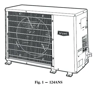
- Fig 1: Overview of the 124ANS unit.
- Fig 2: Proper rigging and lifting technique using a sling.
- Fig 3: Filter drier installation components.
- Fig 4: Line power connection diagram.
- Fig 5: Typical control circuit wiring diagram.
Model compatibility
- Requires Puron (R-410A) compatible equipment.
- Do not use R-22 service equipment or components.
- Requires factory-authorized kits for modifications.
- Polyol Ester (POE) oils are required; do not expose to atmosphere.

Manual page author
Michael Turner
Technical manual editor