Garden / Fencing & Gates
Centurion Anti-Lift Brackets Installation Guide
Installation guide for Centurion Anti-Lift Brackets. Learn how to mount brackets to steel or walls, including welding and screw-fixing methods for sliding gate security.
Table of contents
Manual images
Click an image to enlargeQuick guide from the manual
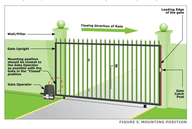
The Centurion Anti-Lift Brackets are designed to enhance the security of sliding gate systems by preventing the gate from being lifted off its track. Critical: Brackets must be mounted at the closest possible point to the Gate Operator when the gate is in the closed position. If there is interference with gate operator magnets, mount the brackets higher on the wall or support post, but no more than 1 meter above the gate operator pinion.
Specifications
The brackets are constructed from mild steel and plated for corrosion protection.
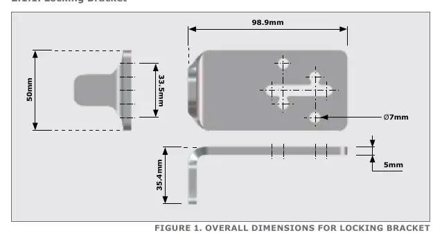
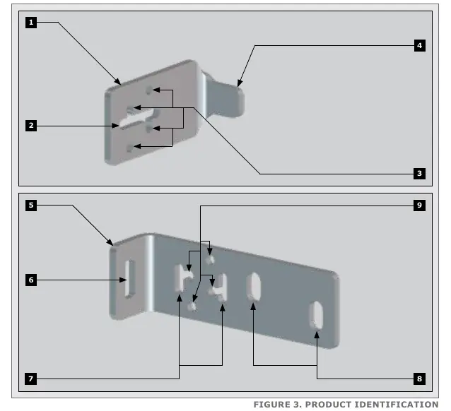
- Locking Bracket: 98.9mm length, 50mm height, 5mm thickness.
- Holding Bracket: 154mm length, 50mm height, 5mm thickness.
- Mounting Holes: 7mm diameter for standard fixing, 11mm diameter for masonry.
Required Tools and Equipment
Ensure you have the following tools before starting installation:
- Welding machine (preferred for steel)
- Electric drill with 6mm steel/masonry bits and 10mm drill bit
- 13mm sockets, socket wrench, and extension
- G-clamps, spirit level, and measuring tape
- Angle grinder and hacksaw
- Safety equipment (goggles, gloves)
- 10mm coach screws (for masonry) or Tek self-drilling screws (for steel)
Installation
Fasteners and hardware are not included with the kit. Test fit the brackets to find the optimal position before final fixing.
Mounting the Holding Bracket
The Holding Bracket can be mounted to walls or support posts:
- Welding: Highly recommended for support posts. Cut off any excess material for a neater finish.
- Tek Screws: Use four M6 high-quality Tek screws for mounting onto support posts.
- Coach Screws: Use two M8 coach screws and wall plugs for mounting onto walls.
Fine-tuning can be achieved by shifting the bracket along the vertical adjustment holes.
Mounting the Locking Bracket
The Locking Bracket is mounted to the gate upright:
- Welding: Highly recommended.
- Tek Screws: Use four M6 high-quality Tek screws.
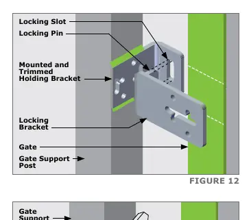
Ensure the locking pin on the Locking Bracket lines up and slots into the locking slot of the Holding Bracket without creating catch points during gate movement. Fine-tuning is possible via the horizontal adjustment holes.
Additional Recommendations
For sites without a catch post on the closing side, a second set of Anti-lift Brackets may be required on the leading edge of the gate. Install these at the same height as the first set. The installation of a Centurion GLX900 Gate lock is also recommended for further security.
Practical help
Common problems
Interference with gate operator magnets
Mount the brackets higher on the wall or support post, ensuring they are no more than 1 meter above the gate operator pinion.
Gate movement catch points
Ensure the locking pin on the locking bracket lines up and slots into the locking slot of the holding bracket without obstruction.
Before use
- Verify the gate is in the closed position.
- Identify the mounting surface (steel or wall).
- Gather required tools: welder, drill, 13mm sockets, spirit level, and safety gear.
- Test fit the brackets to determine optimal orientation.
Specs in practice
- Locking Bracket Dimensions
- 98.9mm length, 50mm height, 5mm thickness.
- Holding Bracket Dimensions
- 154mm length, 50mm height, 5mm thickness.
- Mounting Holes
- 7mm diameter for standard fixing, 11mm diameter for masonry.
Images and diagrams
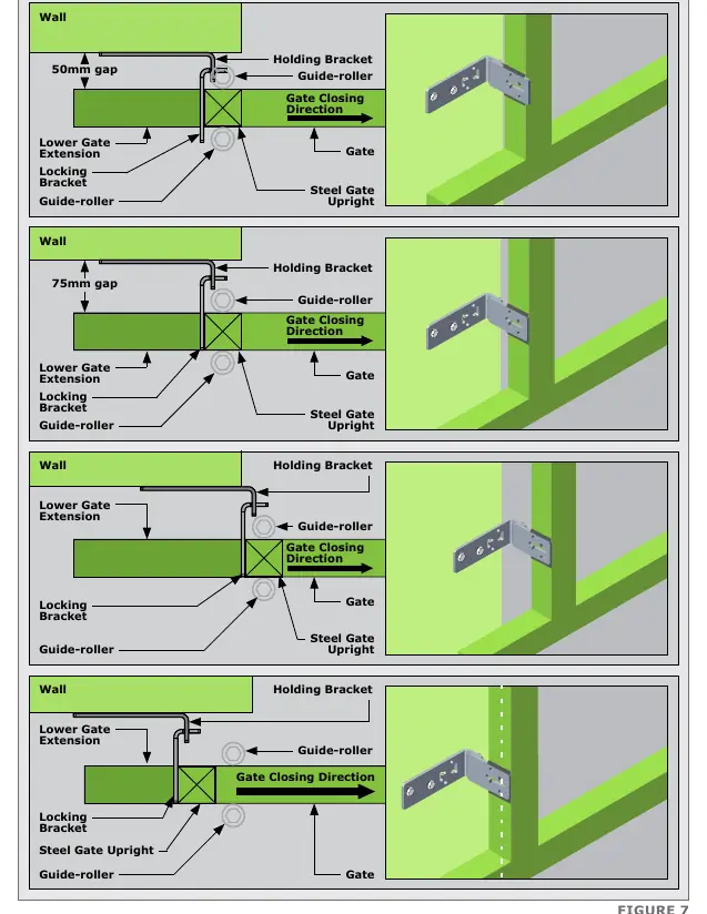
- Figure 5 illustrates the ideal mounting position relative to the gate operator.
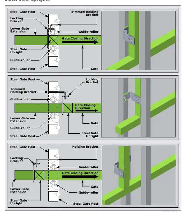
- Figure 6 and 7 show various orientation options for steel uprights and walls.
Model compatibility
- Compatible with standard sliding gate systems.
- Optional GLX900 Gate lock is recommended for additional security.

Manual page author
Emily Carter
User documentation editor
Prepares concise manual descriptions and highlights the most useful setup, operation, and maintenance information for readers.