Garden / Fencing & Gates
Installation manual for G21 Gate Marion 100x173 cm right
Complete installation guide for the G21 Gate Marion 100x173 cm right. Includes safety instructions, required tools, parts list, and step-by-step assembly procedures.
Table of contents
Manual images
Click an image to enlargeImportant information from the manual
This document provides instructions for the installation of the G21 Gate Marion 100x173 cm (right version). Before beginning the assembly, ensure you have read all instructions carefully and verified that all necessary parts are present. The manual is intended for the installation of the gate and should be followed step-by-step to ensure proper assembly.
Safety instructions
- Protective gear: Always wear protective clothing and gloves during assembly, as some components may have sharp edges.
- Work area: Ensure that children and pets are kept away from the working area during the entire assembly process.
Tools required
To assemble the gate, you will need the following tools:
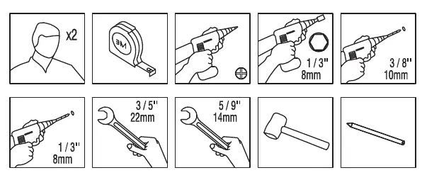
- Tape measure
- Drill with 8mm and 10mm bits
- Wrench (14mm and 22mm)
- Hammer
- Pencil
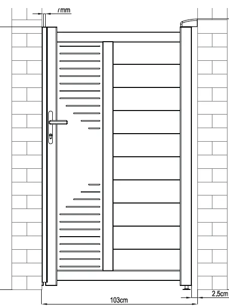
Dimensions
The gate has a total width of 103 cm. The height varies between 176 cm and 181 cm depending on the mounting point. Please refer to the dimension diagram on page 9 for precise measurements.
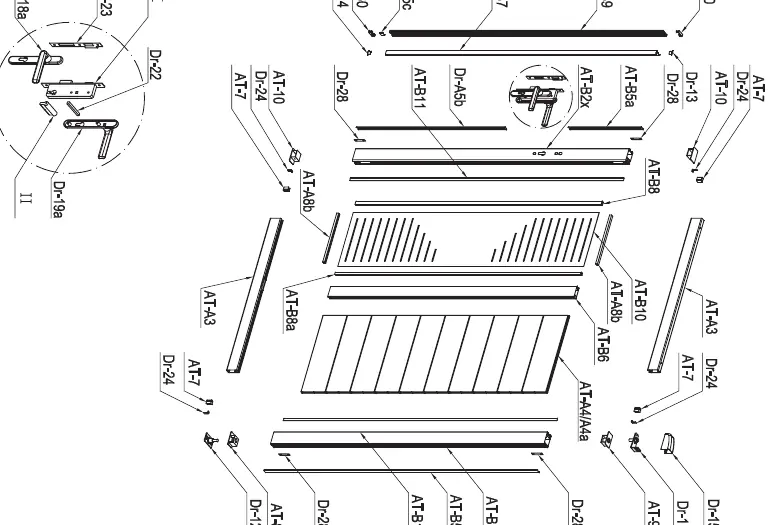
Parts list
The gate consists of numerous components, including frame profiles (AT-B1, AT-B2x, AT-B9, AT-A3, AT-B6, AT-A4, AT-A4a, AT-B10, AT-B8, AT-B8a, AT-A8b, AT-B5, AT-B5a, Dr-A5b, Dr-A5c, AT-B11, AT-7, AT-B7, AT-8, AT-9, AT-10), hinges, locks, and various screws (AT-B30, AT-B31, AT-B32, AT-B33, AT-B34, AT-B35, AT-B36). Refer to the parts list on page 10 to verify all items before starting.
Installation steps
The installation process is divided into 19 steps:
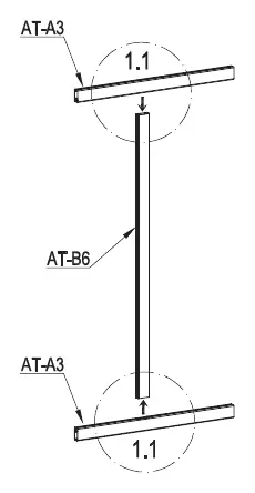
- Frame assembly: Connect the frame profiles (AT-B6 and AT-A3).
- Slat installation: Insert the slats (AT-A4) into the frame.
- Reinforced slat: Install the reinforced slat (AT-A4a) for automation.
- Frame completion: Secure the frame using the provided screws (Dr-28, AT-B33).
- Side panel assembly: Install the side panel (AT-B10) with profiles (AT-B8, AT-B8a, AT-A8b).
- Locking mechanism: Install the lock components (AT-B2x, Dr-28, AT-B33).
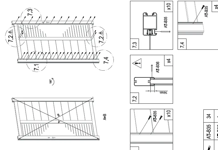
- Final frame assembly: Secure the structure with screws (AT-B35, AT-B36).
- Profile installation: Attach profiles (AT-B11).
- Lock assembly: Install the handle and lock mechanism (AT-B5, AT-B5a, Dr-A5b).
- Hinge installation: Attach hinges (AT-8, AT-9, AT-10, AT-7).
- Handle installation: Mount the handle (Dr-18a, Dr-19a, Dr-22).
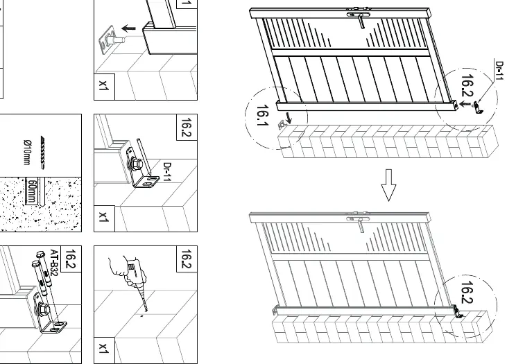
- Wall mounting: Drill holes and mount the gate to the wall using anchors (AT-B34).
- Final adjustments: Install end caps (Dr-13, Dr-14, Dr-30) and finalize the gate position.
- Lock plate: Install the lock plate (Dr-23).
- Bottom hinge: Install the bottom hinge (Dr-12).
- Hinge mounting: Secure the hinges to the wall.
- Alignment: Adjust the gate position.
- Finishing: Install decorative caps (Dr-15, Dr-31).
- Final lock adjustment: Secure the lock (Dr-17).
Care and maintenance
Clean the gate regularly using a rag and water to maintain its appearance and functionality.
Manufacturer information
G21
Practical help
Common problems
Sharp edges on components
Wear protective clothing and gloves during assembly.
Safety hazard during assembly
Keep children and pets away from the working area.
Before use
- Read all instructions carefully.
- Check that all parts listed in the parts list are present.
- Ensure you have the required tools (drill, wrench, hammer, pencil).
- Wear protective clothing and gloves.
Images and diagrams
- Page 11 provides an exploded view of all components for easy identification.
- Pages 12-30 provide detailed, step-by-step visual instructions for the assembly and installation process.
Model compatibility
- This manual is specifically for the 'right' version of the G21 Gate Marion.

Manual page author
Michael Turner
Technical manual editor
Reviews PDF manuals for structure, safety notes, and practical product details so readers can find the right information quickly.