Garden / Fencing & Gates
Installation manual for G21 Reno 100x158 cm Gate
Complete installation guide for the G21 Reno 100x158 cm gate. Includes parts list, assembly steps, wall mounting instructions, and safety guidelines.
Table of contents
Manual images
Click an image to enlargeQuick guide from the manual
Before starting the installation of your G21 Reno gate, ensure you have a clear workspace free of children and pets. Always wear protective clothing and gloves, as some metal components may have sharp edges. Verify that all parts listed in the parts list are present before beginning assembly.
Parts list
The gate assembly consists of various profiles, slats, and hardware. Key components include the main frame profiles (AT-A1), slats (VT-A4), and various screws and brackets (Dr-series). Refer to the parts list on page 10 to identify all components by their codes (e.g., AT-A1, Dr-28, VT-B33) and quantities.
Assembly instructions
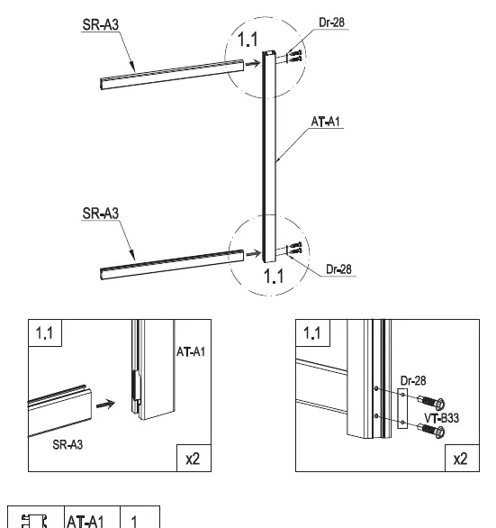
Frame Assembly: Start by connecting the side profiles (AT-A1) with the horizontal supports (SR-A3) using the provided screws (Dr-28, VT-B33). Ensure the frame is square.
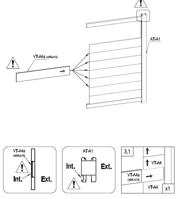
Slat Installation: Insert the slats (VT-A4) into the frame. Note that there is a specific reinforced slat (VT-A4a + SR-A15) intended for automation; ensure this is positioned correctly according to the diagrams on page 14.
Lock and Handle: Install the lock mechanism (Dr-23) and handle (Dr-18a, Dr-19a) into the designated frame profile. Follow the sequence in steps 8.1 through 10.1 to ensure proper alignment and functionality.
Wall mounting
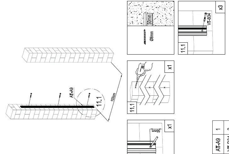
Preparation: Measure the installation width (103cm) and mark the drilling points on the wall. Use a drill with an 8mm or 10mm bit as specified in the diagrams for the wall anchors.
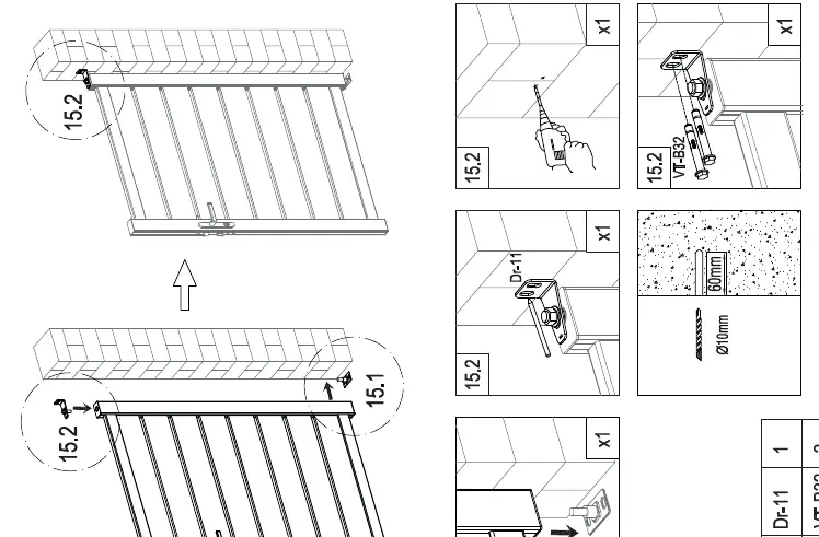
Mounting: Attach the wall brackets (Dr-11, Dr-12) to the wall using the provided anchors (VT-B32). Once the brackets are secure, mount the gate frame onto the hinges. Use the adjustment steps (16.1-16.3) to ensure the gate is level and closes correctly with a gap of 5-7mm.
Care and maintenance
To maintain the gate, clean it regularly using only a soft rag and water. Avoid using harsh chemicals or abrasive cleaners that could damage the finish.
Manufacturer information
G21
Practical help
Common problems
Gate does not close properly
Check the alignment of the hinges and the gap between the gate and the post. Adjust using the mounting brackets as shown in steps 16.1-16.3.
Parts missing
Verify all components against the parts list on page 10 before starting assembly. If parts are missing, do not proceed with installation.
Before use
- Ensure you have all parts listed in the parts list.
- Wear protective clothing and gloves.
- Ensure no children or pets are in the work area.
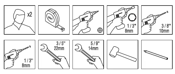
- Prepare necessary tools: tape measure, drill, wrench, hammer, pencil.
- Verify the wall structure is suitable for mounting.
Specs in practice
- Automation Slat
- Specific reinforced slat (VT-A4a) required if installing an automatic gate opener.
Images and diagrams
- Step 1.1: Frame assembly using SR-A3 and AT-A1 profiles.
- Step 3.1: Correct orientation of the reinforced slat for automation.
- Step 11.1: Wall mounting preparation and drilling dimensions.
- Step 16.1-16.3: Final alignment and leveling of the gate.
Model compatibility
- This manual is for the Right-hand configuration gate.

Manual page author
Emily Carter
User documentation editor
Prepares concise manual descriptions and highlights the most useful setup, operation, and maintenance information for readers.