Garden / Fencing & Gates
Natures Composites Modern Ranch Rail Installation Guide
Installation guide for Natures Composites Modern Two-Board and Three-Board Ranch Rail. Includes tools required, post burial and surface mounting instructions, board installation, and top cable setup.
Table of contents
Manual images
Click an image to enlargeQuick guide from the manual
This guide covers the installation of Natures Composites Modern Ranch Rail systems. The system uses a patented U-post design that eliminates the need for specific start, end, or corner posts. Installation primarily involves post burial, though surface mounting is possible with specific modifications. The system is designed for durability and does not require painting.
Before you begin
Before starting, ensure the area is free from underground lines or hazards by contacting local utility services. Verify property lines and consult local building codes to ensure compliance and obtain necessary permits. Always wear appropriate safety equipment, including gloves, safety goggles, and work boots.
Tools required
- Tape measure
- Post hole digger and shovel
- Post bubble level
- Level and string line
- Wheelbarrow
- Stakes or markers
- Torx T20 bit and power tool
Fence location and layout
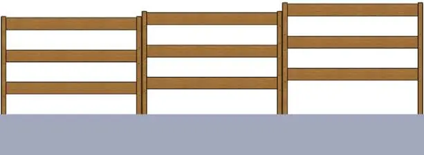
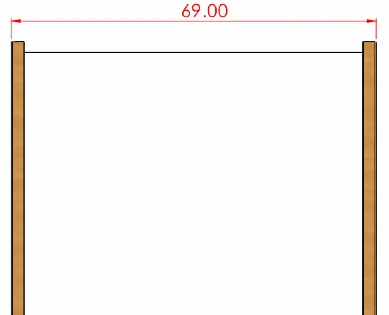
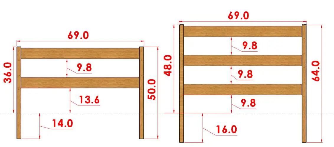
Use stakes and a string line to outline the fence location. Mark the post hole locations for gate posts according to specific gate instructions. Identify corner and end posts. For intermediate fence posts, ensure they are placed no wider than 69 inches (5.75 feet) outside to outside for each fence panel.
Post burial installation
Dig post holes with a 12-inch diameter. The burial depth should be 14 inches for the 2-board model and 16 inches for the 3-board model. For multiple panels, screw line posts back-to-back before burial. Set posts perfectly vertical (plumb) and align them with the string line. Fill holes with concrete (1-2 bags of 60-80 lb per hole). Re-check plumb during curing.
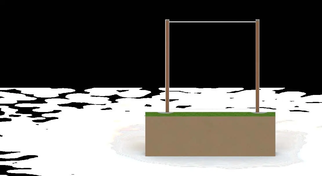
Surface mounting
If burial is not possible, use a metal bracket system. You must use NC Commercial-Grade 5x5 posts between each panel. Secure with a bracket designed for a nominal 4x4 post. Insert a pressure-treated 4x4 wood post inside the composite post to provide structural support. Use composite shims if any gap remains between the bracket and the composite post. Fasteners must pass through the composite post, wood insert, and bracket.
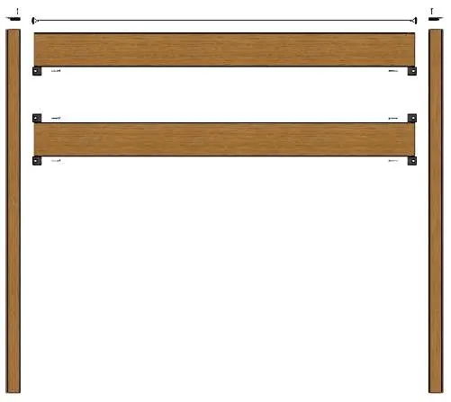
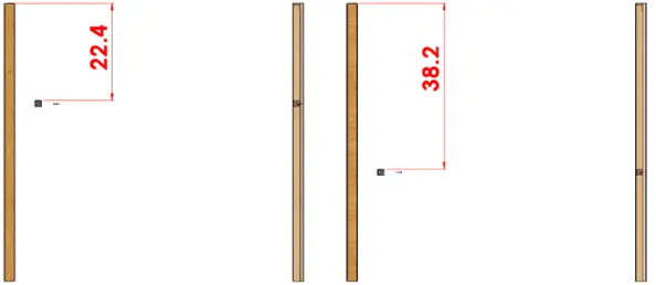
X-Spacer and board installation
Install the first X-Spacer (D) inside the groove of the post (A) at the specified height (22.4 inches for 2-board, 38.2 inches for 3-board) and secure with the included screw. Position the first Edge Square Board (C) between the two U-Posts and lower it until it rests on the X-Spacer. Place the next two X-Spacers on top of the board and secure them. Repeat this process for subsequent boards.
Installing the top cable
The Top Cable (E) secures the boards and maintains post position. Slide the top cable inside the top cavity of the final Square Edge Board. Ensure the H-fasteners are aligned with the U-Post grooves. Insert the last board into the U-channel and ensure the H-fasteners slide into the grooves. Tension the cable as required.
Top cap installation
Position the top cap (B) directly on top of each U-post (A). Insert and tighten the two Top Caps using two 1-5/8 Torx Composite Screws with a Torx T20 bit and power tool.
Maintenance and adjustments
Painting is not advisable as products come pre-finished. Clean occasionally with soap and warm water. If you need to adjust the length, the composite material can be cut with standard wood-cutting tools. You must remove the bottom cable, cut the top cable to the desired length, and reattach the bracket using an aluminum ferrule and a hammer to crimp it.
Practical help
Common problems
Uneven alignment
Ensure all boards are cut at the same place when adjusting length.
Fence instability
Ensure posts are perfectly vertical (plumb) and fully rigid at the base; any play will transfer to the panels.
Surface mounting issues
Use a pressure-treated 4x4 wood insert inside the composite post and use composite shims to ensure a tight fit in the bracket.
Before use
- Verify underground utilities.
- Locate property lines.
- Consult local building codes and obtain permits.
- Wear safety equipment (gloves, goggles, boots).
- Gather required tools (post hole digger, level, power tool).
Specs in practice
- Post burial depth
- 14 inches for 2-board model, 16 inches for 3-board model.
- Post spacing
- 69 inches outside to outside for each fence panel.
- Gate spacing
- 58 inches apart (outside to outside) for proper hinge and latch function.
Images and diagrams
- Post burial diagram shows hole diameter and depth requirements.
- X-Spacer installation diagram shows positioning measurements from the top of the post.
- Top cable installation shows how to slide the cable into the final board cavity.
Model compatibility
- Painting is not recommended; clean with soap and warm water.
- Surface mounting may void the warranty for structural issues.
- For gates, you must use two NC 5x5 Commercial Posts.

Manual page author
Emily Carter
User documentation editor
Prepares concise manual descriptions and highlights the most useful setup, operation, and maintenance information for readers.