Automotive / Motor Controllers
Installation and Troubleshooting Guide for Curtis 1206AC E-Z-GO RXV Controller
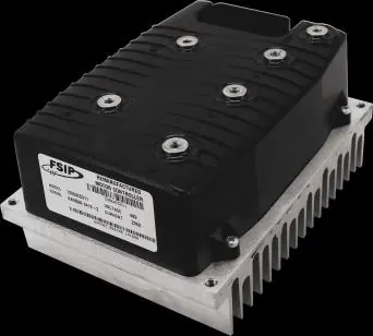
A comprehensive installation and troubleshooting guide for the Curtis 1206AC E-Z-GO RXV controller. Includes mandatory pre-installation checks, wiring diagrams, power-up sequences, and detailed fault code analysis.
Table of contents
Manual images
Click an image to enlargeImportant Pre-Installation Information
Warning: Warranty will be void if the following steps are not performed before installing the control. This sheet is provided to aid in the installation of your remanufactured CURTIS controller. An analog or digital volt ohm meter (VOM) is required for these checks.
Pre-Installation Checks
Before installing the controller, you must verify the following components to prevent immediate controller failure:
- Motor Phases: With the motor disconnected, measure resistance between U-V, V-W, and W-U. Each should measure between 0.5Ω and 1Ω. Measure U, V, & W to the motor frame; this must be greater than 5MΩ.
- Main Solenoid: Disconnect all wires. Measure the solenoid coil resistance; it should be between 95 and 115 ohms. When energized with jumpers, the meter must jump from infinity to less than 0.3Ω.
- Brake Coil: Measure the brake coil resistance at room temperature; it should be approximately 25Ω.
- Wire Harness: Inspect all connectors for corrosion, loose, broken, burnt, or missing pins. Repair or replace as necessary.
Wiring and Connections
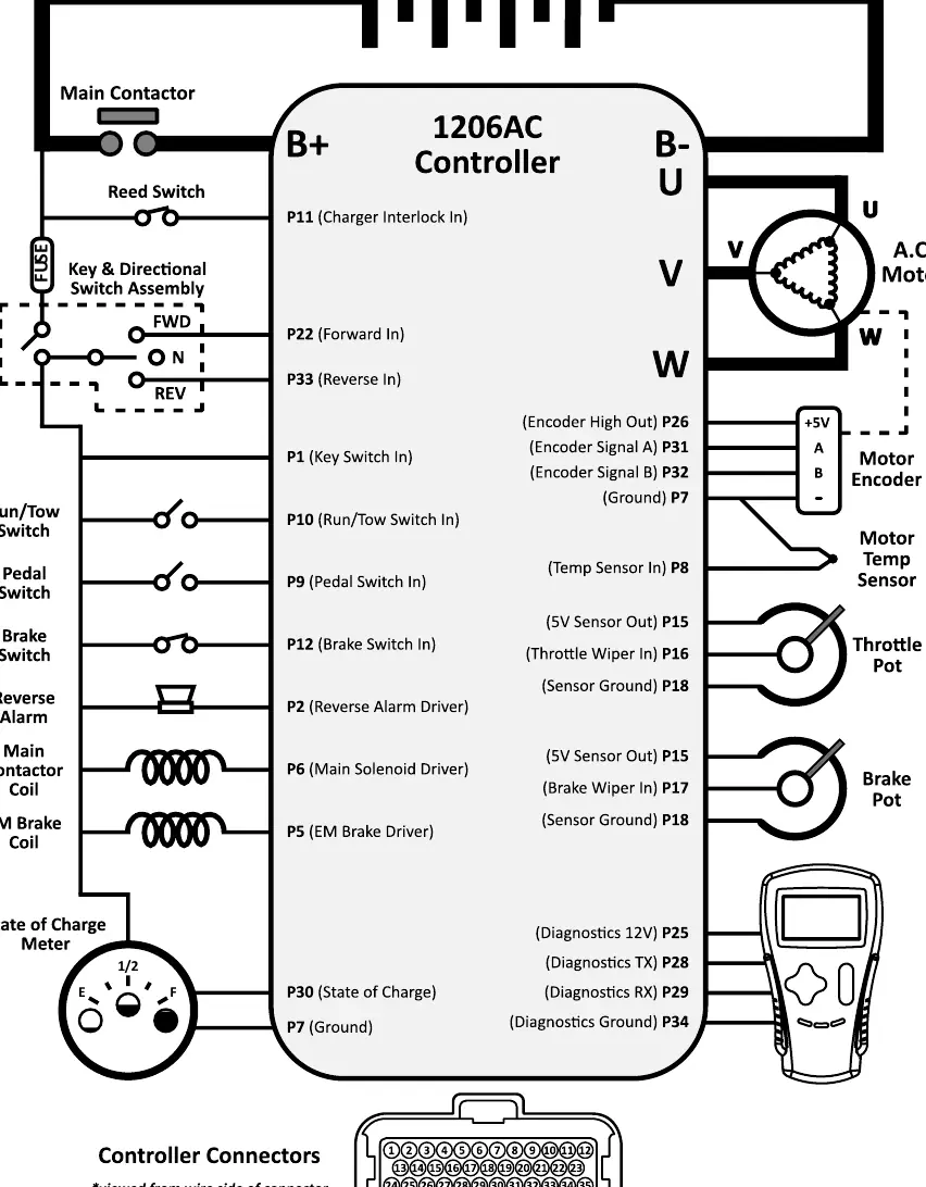
Refer to the wiring diagram for proper connection of the 48V battery pack, motor, encoder, sensors, and diagnostic port. Ensure all connections are secure and match the pinout specifications provided in the diagram.
RXV Power-Up Sequence
During the first second after turning the key on, the vehicle performs several system checks. If any issues are detected, the vehicle will not operate:
- Electric Brake Test: Controller attempts to rotate the motor a quarter turn in each direction.
- Reverse Alarm Test: Alarm activates for 100 milliseconds.
- Charger Connection Test: Verifies if the charging port is connected.
- Throttle Switch Verification: Switch must be in the "open" position.
- Throttle Position Check: Sensor must indicate 0% throttle.
- Throttle Range Test: Confirms TPS operates within expected range.
Troubleshooting Sequence
Safety: Always lift the drive wheels off the ground when troubleshooting. Use a voltmeter with the negative lead on the main battery. Perform these tests with the connector attached to the controller by 'back probing' the pins.
Follow this sequence (do not skip steps):
- Pin 11: With charger disconnected, must be >16V.
- Pin 10: With Tow/Run in Run, must be approx 0V.
- Pin 1: With Key Switch in Forward/Reverse, must be approx Pack Voltage.
- Pin 22/33: With Key Switch in Forward/Reverse, must be approx Pack Voltage.
- Pin 2: With Key Switch in Reverse, must be approx 0V (buzzer should sound).
- Pin 9: Pedal switch checks (0V when not engaged, Pack Voltage when engaged).
- Pin 12: Brake switch checks (Pack Voltage when not engaged, 0V when engaged).
- Pin 6: With Key Switch engaged, must be approx 0V (solenoid should engage).
- Pin 15/18: Sensor voltage checks (15 should be 5V, 18 should be 0V).
- Pin 16/17: Throttle/Brake pedal voltage (0.5V to 4.8V).
Fault Codes and Troubleshooting
The system provides various fault codes to assist in diagnostics. Common faults include:
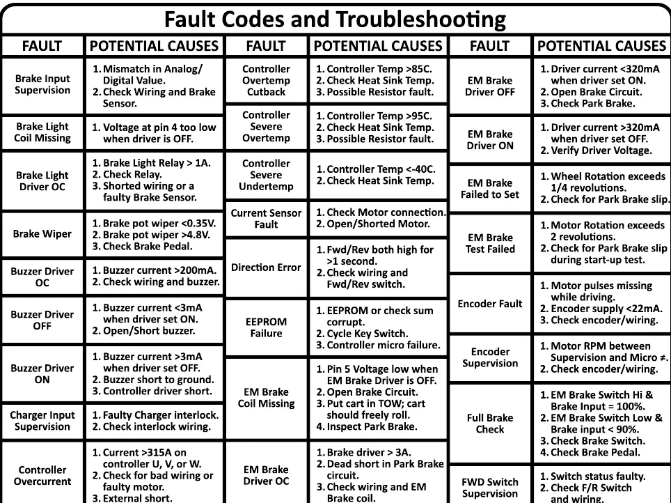
- Controller Overtemp: Check if temperature is >85C and inspect heat sink.
- Brake Wiper: Check brake pot wiper voltage (should be 0.35V-4.8V).
- EM Brake Coil Missing: Check for open brake circuit.
- Main Contactor Issues: Check for voltage drops or welded contacts.
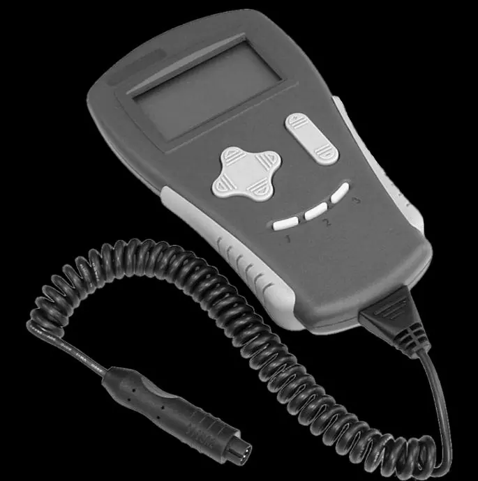
For advanced programming, testing, and parameter adjustments, use the Curtis Handheld Diagnostic unit. Do not use the CAN plug located under the 4 cup console.
Practical help
Common problems
Controller fails to operate
Check fault codes, verify battery voltage, check solenoid and brake coil resistance.
Controller Overtemp fault
Check if controller temperature is >85C and inspect heat sink.
Brake Wiper fault
Verify brake pot wiper voltage is between 0.35V and 4.8V.
Main Contactor does not close
Check for voltage drop across contacts and ensure battery voltage is sufficient.
Before use
- Check motor phases (U, V, W) resistance (0.5Ω - 1Ω).
- Measure solenoid coil resistance (95 - 115 ohms).
- Measure brake coil resistance (approx 25Ω).
- Inspect wire harness for corrosion or loose pins.
- Ensure battery pack voltage is good.
- Lift drive wheels off the ground before troubleshooting.
Specs in practice
- Motor Resistance (U, V, W)
- 6.8 – 8.36 milliohms (Note: most DVMs will not read this).
- Solenoid Coil Resistance
- 95 – 115 ohms.
- Brake Coil Resistance
- Approx 25Ω at room temperature.
- Throttle/Brake Pedal Voltage
- 0.5V (up) to 4.8V (fully depressed).
Images and diagrams
- Wiring Diagram: Shows connections for 48V battery pack, motor, encoder, sensors, and diagnostic port.
- Pinout: Detailed pin assignments for the 1206AC controller.
Model compatibility
- Designed for E-Z-GO RXV vehicles.
- Requires Curtis Handheld Diagnostic unit for advanced programming.
- Do not use the CAN plug located under the 4 cup console.

Manual page author
Emily Carter
User documentation editor
Prepares concise manual descriptions and highlights the most useful setup, operation, and maintenance information for readers.