Automotive / Motor Controllers
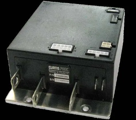
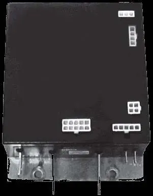
Curtis 1206MX PDS Motor Controller Installation Guide
Installation and troubleshooting guide for the Curtis 1206MX PDS motor controller. Includes essential pre-installation motor and solenoid resistance checks, pin-by-pin voltage testing procedures, diagnostic beep code interpretation, and...
Table of contents
Manual images
Click an image to enlargeQuick guide for installation and troubleshooting
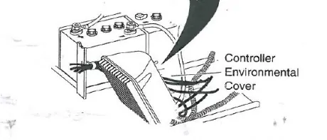
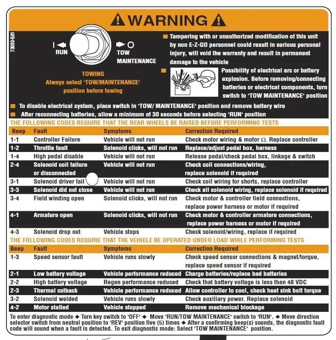
This document provides critical pre-installation checks and troubleshooting procedures for the Curtis 1206MX PDS controller. Failure to perform these checks before installation may void the warranty and cause controller failure. Always lift the drive wheels off the ground when troubleshooting.
Pre-installation checks
Before installing the controller, perform the following tests using a VOM (Volt Ohm Meter):
- Motor Windings: Disconnect the motor and measure resistance. A1 to A2 must be between 0.3Ω and 1Ω. F1 to F2 must be between 1Ω and 2Ω. A1 to F1 must be OPEN. F1 to motor case must be greater than 5MΩ.
- Main Solenoid: Disconnect all wires. Measure the solenoid coil resistance; it must be no less than 100Ω. Connect VOM leads to lugs and attach jumpers from the battery to the coil; the meter must jump from infinity to less than 0.3Ω.
- Cotherm: Inspect the insulating material on the heat sink for holes, debris, or tears. Repair or replace if necessary.
- Wire Harness: Check all connectors for corrosion, loose, broken, burnt, or missing pins.
Troubleshooting sequence
All tests are conducted with the Run-Tow/Maintenance switch in the RUN position and the connector attached to the controller. Use a paperclip to 'back probe' the pins from the wire side of the connector.
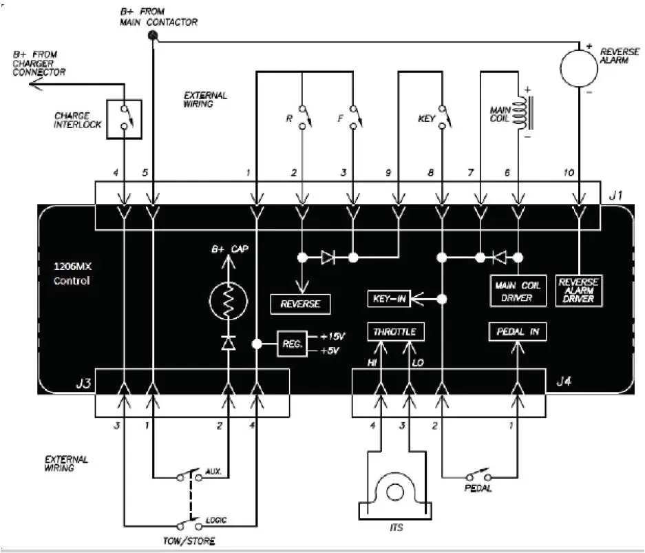
- Pack Voltage: Measure voltage at the main battery positive post.
- J1 Pin 5: Must be within 4 volts of Pack Voltage.
- J3 Pin 2: Must be the same voltage as J1 Pin 5.
- J1 Pin 4: With charger disconnected, must be at Pack Voltage.
- J3 Pin 4: Must be equal to Pack Voltage.
- J1 Pin 1: Must be equal to Pack Voltage.
- F/R Switch Checks: Verify voltages at J1 pins 2, 3, 9, and 10 based on switch position (Neutral, Forward, Reverse).
- Pedal/Sensor Checks: Verify J4 and J5 pin voltages based on pedal position and speed sensor operation.
Diagnostic mode
The controller features a diagnostic mode that uses the back-up alarm to beep out fault codes. To enter diagnostic mode: Turn key switch to OFF, move Run/Tow switch to RUN, and move the direction selector switch from neutral to REV five times. The controller will beep the fault code when a fault is detected.
Helpful hints
Many cart issues are caused by burnt or damaged motor brushes. Ensure the armature and field within the motor are not shorted, as this will damage the controller. It is recommended to replace the solenoid at the time of controller replacement.
Practical help
Common problems
Vehicle will not run
Check motor wiring and resistance, solenoid coil, pedal box, and harness.
Vehicle runs slowly
Check speed sensor connections, magnet, and torque. Replace speed sensor if required.
Solenoid clicks but vehicle won't run
Check pedal box, linkage, and switch.
Controller failure (Beep code 1-1)
Check motor wiring and motor resistance. Replace controller if necessary.
Before use
- Lift drive wheels off the ground.
- Set VOM to resistance mode.
- Measure motor windings (A1-A2, F1-F2, A1-F1, F1-Case).
- Test main solenoid coil resistance.
- Inspect cotherm material on heat sink.
- Check wire harness connectors for damage.
Specs in practice
- A1-A2 Resistance
- Must be between 0.3Ω and 1Ω.
- F1-F2 Resistance
- Must be between 1Ω and 2Ω.
- Solenoid Coil Resistance
- Must be no less than 100Ω.
- Speed Sensor Voltage
- Should toggle between 0 and 5 volts when wheel is turned slowly.
Images and diagrams
- Wiring Diagram: Illustrates connections for J1, J3, J4, and J5 connectors.
- Diagnostic Warning Label: Provides instructions for entering diagnostic mode and a table of fault codes.
Model compatibility
- Designed for E-Z-GO PDS systems.
- Requires specific resistance ranges for motor and solenoid to avoid controller failure.

Manual page author
David Miller
Documentation analyst
Organizes user manual content into clear summaries, with attention to model details, product context, and everyday usability.