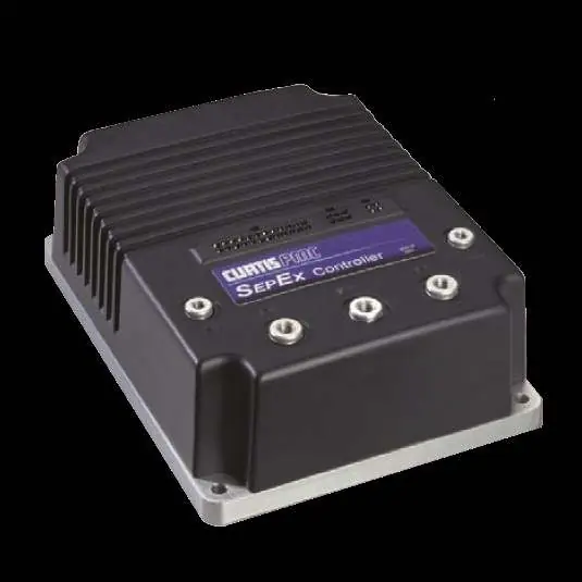
Automotive / Motor Controllers
Installation and Troubleshooting Guide for Curtis 1268-ITS Controller
Comprehensive installation and troubleshooting guide for the Curtis 1268-ITS motor controller. Includes essential pre-installation checks, wiring diagrams, pin-by-pin voltage testing procedures, and LED fault code diagnostics to ensure...
Table of contents
Manual images
Click an image to enlargeQuick Guide from the Manual
This document provides critical pre-installation checks and troubleshooting procedures for the Curtis 1268-ITS controller. Warning: Failure to perform the specified pre-installation checks will void the warranty and may cause controller failure. Always lift the drive wheels off the ground when troubleshooting.
Pre-Installation Checks
Before installing the controller, perform the following tests using a Volt Ohm Meter (VOM):
- Motor Windings: With the motor disconnected, measure resistance between A1-A2 (0.2Ω to 2Ω), F1-F2 (0.8Ω to 3Ω), A1-F1 (Open), and F1 to motor case (>5MΩ).
- Main Solenoid: Disconnect all wires. Measure coil resistance (100Ω to 250Ω). When energized, resistance should drop from infinity to less than 0.3Ω.
- Wire Harness: Inspect all connectors for corrosion, loose, broken, burnt, or missing pins. Repair or replace as necessary.
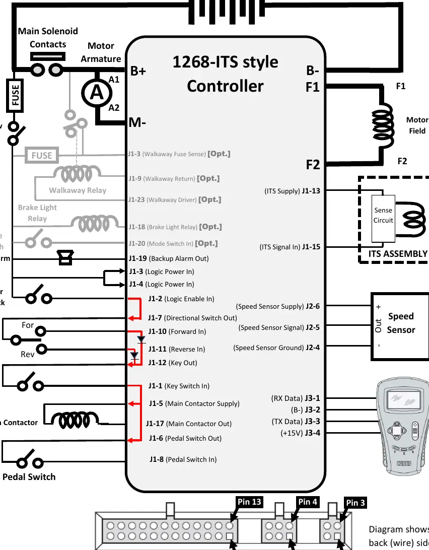
Wiring and Connections
The controller requires specific connections for the battery pack, motor armature, motor field, speed sensor, and various switches (Run/Tow, Mode, Key, Pedal). Ensure all connections match the provided wiring diagram, specifically noting the pin assignments for the J1, J2, and J3 connectors.
Troubleshooting Sequence
When troubleshooting, ensure the Run/Tow switch is in the RUN position and the connector is attached to the controller. Use a paperclip to 'back probe' the pins from the wire side of the connector. Follow this sequence:
- Power Checks: Verify Pack Voltage at pins J1-3 and J1-4.
- Charger Interlock: Verify Pack Voltage at J1-2 and J1-7 with the charger disconnected.
- Directional Switches: Check F/R switch inputs at J1-10 and J1-11.
- Key Switch: Verify Pack Voltage at J1-1, J1-5, J1-17, and J1-6 when the key is ON.
- Pedal Switch: Verify voltage at J1-8 (0V with pedal up, Pack Voltage with pedal down).
- ITS Sensor: Verify 14-15V at J1-13. Check signal at J1-15 (approx. 0.8V pedal up, 2.0V pedal fully depressed).
LED Diagnostics
The controller features a built-in Status LED that flashes 2-digit fault codes. Common codes include:
- 1,2: Throttle Fault (ITS signal out of range).
- 1,3: Speed Sensor Fault (No pulses).
- 2,3: Thermal Cutback (Over/under temperature).
- 3,2: Main Welded (Main contactor stuck closed).
- 3,4: Field Missing (Motor field wiring loose or open).
Helpful Hints
Do not underestimate the importance of motor resistance checks. Many cart issues are caused by burnt or damaged brushes. A shorted armature or field within the motor will damage the controller. If you encounter issues, consult the full troubleshooting chart for specific fault explanations and causes.
Practical help
Common problems
LED Code 1,2 (Throttle Fault)
Check for open throttle input wire, wire shorted to B+/B-, or defective ITS sensor.
LED Code 1,3 (Speed Sensor Fault)
Ensure speed sensor is connected, not defective, and the magnet is not damaged.
LED Code 2,3 (Thermal Cutback)
Check for excessive load, improper mounting, or operation in extreme environments (temp > 85°C or < 25°C).
LED Code 3,2 (Main Welded)
Main contactor is stuck closed or the driver is shorted.
Controller fails to operate
Verify all pre-installation checks (motor windings, solenoid, harness) were performed correctly.
Before use
- Lift drive wheels off the ground.
- Set VOM to Resistance (Ω).
- Measure motor A1 to A2 (0.2Ω - 2Ω).
- Measure motor F1 to F2 (0.8Ω - 3Ω).
- Measure solenoid coil (100Ω - 250Ω).
- Inspect wire harness for corrosion or loose pins.
- Ensure Run/Tow switch is in RUN position.
Specs in practice
- A1 to A2 Resistance
- Motor Armature resistance; should be 0.2Ω to 2Ω.
- F1 to F2 Resistance
- Motor Field resistance; should be 0.8Ω to 3Ω.
- Solenoid Coil
- Resistance should be 100Ω to 250Ω.
- ITS Signal (Pedal Up)
- Voltage should be approximately 0.8V (+/- 0.3V).
- ITS Signal (Pedal Down)
- Voltage should be approximately 2.0V (+/- 0.3V).
Images and diagrams
- Wiring diagram illustrates connections for battery pack, motor armature, motor field, main solenoid, speed sensor, and controller pins J1, J2, J3.
Model compatibility
- Compatible with 36V/48V battery packs.
- Designed for Curtis 1268-ITS style controllers.
- Optional features (Walkaway, Brake Light, Mode Switch) may not be present on all carts.

Manual page author
Emily Carter
User documentation editor
Prepares concise manual descriptions and highlights the most useful setup, operation, and maintenance information for readers.