Automotive / Motor Controllers
Curtis 1264-ITS Motor Controller Installation and Troubleshooting Guide
A comprehensive installation and troubleshooting guide for the Curtis 1264-ITS motor controller. Includes essential pre-installation checks, wiring diagrams, pin-by-pin voltage testing procedures, and a detailed fault code diagnostic chart.
Table of contents
Manual images
Click an image to enlargeQuick Guide: Pre-Installation Requirements
Before installing the Curtis 1264-ITS controller, you must perform specific diagnostic checks to ensure the cart and motor are in good working condition. Failure to perform these checks may void the warranty and cause controller failure.

- Motor Winding Check: Disconnect the motor and use a VOM (Volt Ohm Meter) to measure resistance. A1 to A2 should be 0.2Ω–2Ω; F1 to F2 should be 0.8Ω–3Ω; A1 to F1 should be OPEN; F1 to motor case should be greater than 5MΩ.
- Main Solenoid Check: Disconnect all wires. Measure the solenoid coil resistance, which should be 100Ω–250Ω. When energized, the meter should jump from infinity to less than 0.3Ω.
- Wire Harness Inspection: Check all connectors for corrosion, loose, broken, burnt, or missing pins. Repair or replace as necessary.
Wiring and Connections
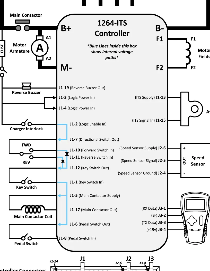
The controller features various inputs and outputs for system integration. Key connections include the battery pack (B+ and B-), motor armature (A1, A2), motor fields (F1, F2), and various logic inputs such as the Key Switch, Pedal Switch, and Forward/Reverse (F/R) switches. Ensure all connections match the wiring diagram provided in the manual.
Troubleshooting Sequence
For safety, always lift the drive wheels off the ground when troubleshooting. Perform these tests with the Run-Tow/Maintenance switch in the RUN position and the connector attached to the controller. Use a paperclip to 'back probe' the pins from the wire side of the connector.
Key Voltage Tests:
- Pin J1-3 & J1-4: Must be Pack Voltage with the cart in Run.
- Pin J1-2 & J1-7: Must be Pack Voltage with the charger disconnected.
- Pin J1-10 & J1-11: Used for F/R switch logic; must toggle between 0 volts and Pack Voltage depending on switch position.
- Pin J1-1, J1-5, J1-17: Must be Pack Voltage when the Key Switch is ON.
- Pin J1-8: Pedal switch input; must be 0 volts (Pedal Up) and Pack Voltage (Pedal Down).
- Pin J1-15: ITS sensor input; should be approximately 1V (Pedal Up) to 3.5V (Pedal Fully Depressed).
Fault Codes and Diagnostics
The controller features a built-in Status LED visible through a window on the label. When a fault is detected, the LED flashes a 2-digit code continuously. For example, code 3,2 (welded main contactor) appears as three flashes, a pause, and two flashes.
Common Faults:
- 1,1 HW FAILSAFE: Controller defective.
- 1,2 THROTTLE FAULT 1: Wiper signal out of range (ITS fault).
- 1,3 SPEED SENSOR FAULT: No pulses from speed sensor.
- 1,4 HPD: High Pedal Disable fault.
- 1,5 MOTOR STALL: Motor stall at current.
- 2,1 LOW BATTERY VOLTAGE: Battery voltage below threshold or corroded terminal.
- 2,2 OVERVOLTAGE: Battery voltage too high or vehicle operating with charger attached.
- 2,3 THERMAL CUTBACK: Temperature out of range or excessive load.
- 3,2 MAIN WELDED: Main contactor stuck closed.
- 4,3 M- SHORTED: Internal M- short to B-.
Practical help
Common problems
Controller fails to operate
Check fault codes via the Status LED, verify battery voltage, and ensure all wiring connections are secure.
Motor stall
Check for steep slopes, mechanically locked motor, EM brake wiring faults, or a defective speed sensor.
Main contactor not closing
Check solenoid wiring and coil resistance. Replace solenoid if necessary.
ITS sensor out of range
Verify voltage at Pin J1-15. If out of tolerance, the ITS sensor may be defective and require replacement.
Before use
- Set VOM to resistance mode.
- Measure motor windings (A1-A2, F1-F2, A1-F1, F1-case).
- Check main solenoid coil resistance (100-250 ohms).
- Inspect wire harness for corrosion or loose pins.
- Lift drive wheels off the ground before troubleshooting.
- Ensure Run-Tow/Maintenance switch is in the RUN position.
Specs in practice
- A1 to A2 resistance
- Should be between 0.2 and 2 ohms.
- F1 to F2 resistance
- Should be between 0.8 and 3 ohms.
- Solenoid coil resistance
- Should be 100-250 ohms.
- ITS Sensor Voltage (Pedal Up)
- Approximately 1V (+/- 0.3V).
- ITS Sensor Voltage (Pedal Down)
- Approximately 3.5V (+/- 0.3V).
Images and diagrams
- The wiring diagram illustrates the connections for the 36/48V battery pack, motor armature, motor fields, and various logic inputs including the Key Switch, Pedal Switch, and Forward/Reverse switches.
- It highlights the internal voltage paths and pin assignments for connectors J1, J2, and J3.
Model compatibility
- Designed for 36/48V battery packs.
- Requires specific solenoid replacement (White Rodgers solenoids recommended).
- If a suppression diode is present, the non-banded side must go to the wire from J1 pin 17.

Manual page author
David Miller
Documentation analyst
Organizes user manual content into clear summaries, with attention to model details, product context, and everyday usability.