Industrial / Electrical
Installation Guide for Danfoss 027F3374 PM Overhaul Kit
A comprehensive guide for the Danfoss 027F3374 PM Overhaul Kit, detailing component identification, quantities, and assembly diagrams for PM size 40 valves.
Table of contents
Quick guide from the manual
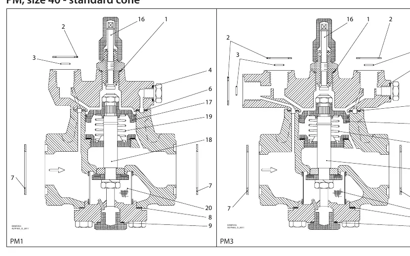
This document serves as an installation and spare parts reference for the Danfoss 027F3374 Overhaul Kit, designed for PM size 40 valves with a standard cone. It provides a visual breakdown of all components included in the kit, their specific dimensions, material types (Aluminum or Fibre), and the required quantity for assembly.
Component Identification and Assembly
The kit contains various seals, gaskets, and internal valve components. The assembly diagrams for PM1 and PM3 configurations illustrate the placement of these parts. Users should refer to the numbered diagrams to ensure correct positioning of components 1 through 20 during the overhaul process.
Parts List and Specifications
The kit includes the following components, identified by their reference numbers:
- 1: Alu seal, Ø26 mm (1.02") - Total: 1
- 2: Fibre seal, Ø33 mm (1.28") - Total: 4
- 3: Fibre seal, Ø9 mm (0.36") - Total: 3
- 4: Alu seal, Ø18 mm (0.70") - Total: 1
- 5: Alu seal, Ø14 mm (0.55") - Total: 1
- 6: Fibre seal, Ø93 mm (3.66") - Total: 1
- 7: Fibre seal, Ø65 mm (2.56") - Total: 2
- 8: Fibre seal, Ø78 mm (3.07") - Total: 1
- 9: Alu seal, Ø32 mm (1.26") - Total: 1
- 10: Alu seal, Ø22 mm (0.87") - Total: 1
- 16, 17, 18, 19, 20: Various internal valve components and springs as shown in the assembly diagram.
Note: Part 10 is included in the package but is not used for PM 1 or PM 3 with a standard cone.
Manufacturer information
Danfoss A/S
Practical help
Common problems
Part 10 is left over after assembly.
This is normal; part 10 is included in the kit but is not used for PM 1 or PM 3 valves with a standard cone.
Before use
- Verify the valve model is PM size 40 with a standard cone.
- Ensure all parts listed in the kit are present before starting disassembly.
- Identify the correct material (Alu vs Fibre) for each seal during installation.
- Cross-reference the numbered parts with the PM1/PM3 assembly diagrams.
Specs in practice
- Alu vs Fibre
- Material designation for seals; ensure the correct material is used in the designated location.
Images and diagrams
- The diagrams show the cross-section of PM1 and PM3 valves with numbered parts corresponding to the kit contents.
- Arrows indicate the flow direction and orientation of internal components.
Model compatibility
- Designed specifically for PM size 40 valves with standard cone.
- Some parts (e.g., part 10) are not compatible with all configurations.

Manual page author
David Miller
Documentation analyst
Organizes user manual content into clear summaries, with attention to model details, product context, and everyday usability.