Industrial / Electrical
Danfoss 027F3375 Overhaul Kit Installation Guide
Quick guide for the Danfoss 027F3375 overhaul kit for PM size 50 valves. Includes component identification, material specifications, and quantity lists for PM1 and PM3 configurations.
Table of contents
Quick guide from the manual
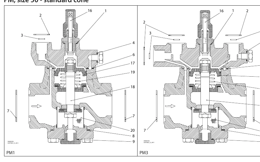
This document provides the component breakdown and identification for the Danfoss 027F3375 overhaul kit, designed for PM size 50 valves with a standard cone. It serves as a reference for identifying parts and their respective materials (Aluminum or Fibre) during maintenance or repair of PM1 and PM3 valve models.
Component Identification
The kit contains various seals, gaskets, and internal valve components. Each part is numbered and corresponds to the assembly diagrams for PM1 and PM3 models. Users should verify the contents of the kit against the provided list to ensure all necessary parts are present before beginning the overhaul.
Material Specifications and Quantities
The following components are included in the kit. Note that some parts are material-specific (Alu. or Fibre):
- Part 1: Alu, Ø26 mm (1.02"), Qty: 1
- Part 2: Fibre, Ø33 mm (1.28"), Qty: 4
- Part 3: Ø9 mm (0.36"), Qty: 3
- Part 4: Alu, Ø18 mm (0.70"), Qty: 1
- Part 5: Alu, Ø14 mm (0.55"), Qty: 1 (Note: Included in package but not used for PM1/PM3 standard cone)
- Part 6: Fibre, Ø105 mm (4.13"), Qty: 1
- Part 7: Fibre, Ø76 mm (2.99"), Qty: 2
- Part 8: Fibre, Ø92 mm (3.62"), Qty: 1
- Part 9: Alu, Ø32 mm (1.26"), Qty: 1
- Part 10: Alu, Ø22 mm (0.87"), Qty: 1 (Note: Included in package but not used for PM1/PM3 standard cone)
- Part 16: Valve stem assembly
- Part 17: Valve seat/housing component, Ø85 mm (3.35")
- Part 18: Internal valve shaft assembly, Ø50 mm (1.97")
- Part 19: Spring, Ø49 mm (1.93"), Qty: 1
- Part 20: Filter/Screen, Ø74 mm (2.91"), Qty: 1
Manufacturer information
Danfoss A/S
Practical help
Common problems
Part 5 or Part 10 left over after assembly
These parts are included in the kit but are not used for PM1 or PM3 valves with a standard cone.
Before use
- Verify the valve model is PM size 50 with a standard cone.
- Cross-reference all parts against the provided diagram numbers (1-20).
- Ensure the correct material (Alu. vs Fibre) is used for each specific seal location.
- Check quantities of each part to ensure the kit is complete.
Images and diagrams
- The diagram shows the internal assembly of PM1 and PM3 valves.
- Numbers 1 through 20 point to specific components within the valve assembly.
- The table below the diagram provides the physical diameter (mm and inches) and quantity for each numbered part.
Model compatibility
- Designed specifically for PM size 50 valves with a standard cone.
- Not all parts in the kit are used for every configuration (see Part 5 and 10 notes).

Manual page author
Emily Carter
User documentation editor
Prepares concise manual descriptions and highlights the most useful setup, operation, and maintenance information for readers.