Software / Apps Services
Installation Instructions for Danfoss HG12P Additional Fan
Quick guide for installing and connecting the Danfoss additional fan for various compressor models, including mounting procedures, electrical connection diagrams, and safety requirements.
Table of contents
Quick guide from the manual
This document provides installation instructions for the Danfoss additional fan designed for various compressor models. The primary task involves mounting the fan bracket to the cylinder cover and securing the fan unit. Before starting, ensure the voltage and frequency of the power supply match the specifications on the fan's nameplate.
Installation
The fan is mounted directly onto the cylinder cover of the compressor. The general procedure is as follows:
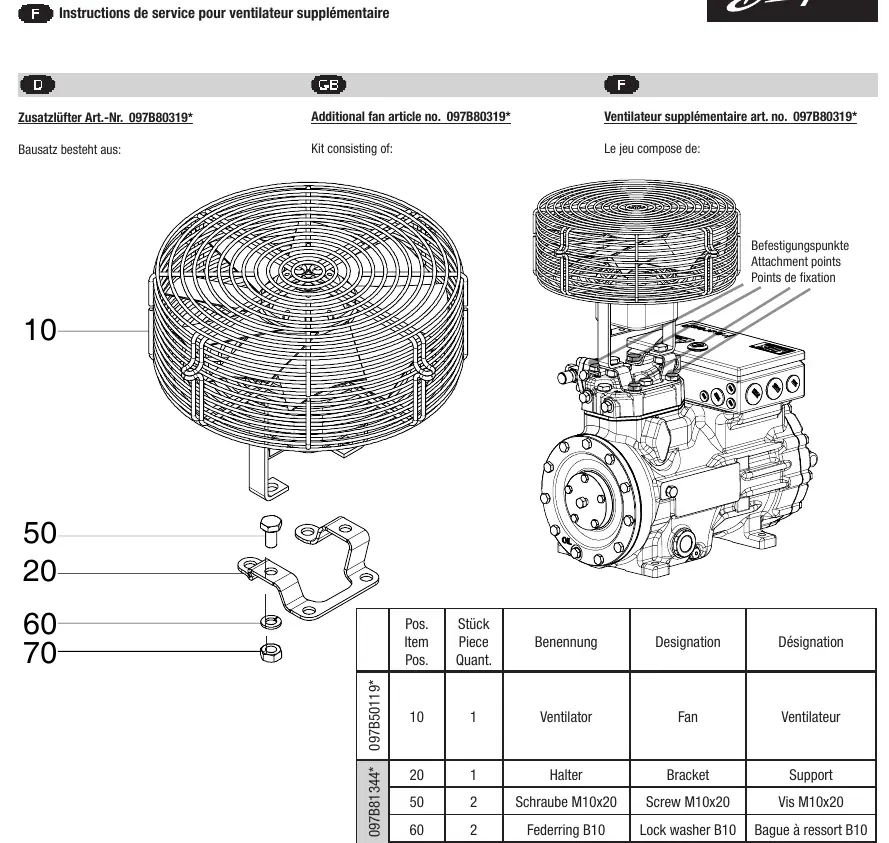
- Identify the correct attachment points on the cylinder cover.
- Replace existing cylinder cover screws with the provided screws and spacers (if applicable to your specific model kit).
- Mount the bracket (item 20) securely to the cylinder cover.
- Fasten the fan (item 10) to the bracket using the provided attachment hardware (screws, washers, lock washers, and nuts).
Refer to the specific page in the manual corresponding to your compressor model (e.g., HG12P, HG22P/e, HG34P/e, HG4/5/6, HG7/F16, HG66e/F76, HG8/88e/F18/F88, or F3/F4/F5) to identify the exact parts and screw sizes required for your assembly.
Electrical Connection
The fan must be connected according to the provided wiring diagram. Ensure the motor is only started when the voltage and frequency comply with the nameplate data. The wiring color code is as follows:
- L (U1): Blue
- Z: Brown
- N (U2): Black
- PE: Green / Yellow
- TOP: Gray
Safety and Maintenance
The motor must only be operated if the voltage and frequency match the specifications. Always verify the compatibility of the kit with your specific compressor model before installation. Legacy BOCK reference numbers do not include the '097B' prefix.
Manufacturer information
Danfoss A/S
Practical help
Common problems
Motor does not start or runs incorrectly
Verify that the power supply voltage and frequency match the data on the fan's nameplate.
Incorrect screw length during installation
Ensure you are using the specific screws and spacers listed for your compressor model (e.g., HG4, HG5+6, HG7, etc.) as detailed in the respective model section.
Before use
- Compare nameplate data with existing voltage and frequency.
- Verify the kit article number matches your compressor model.
- Ensure all necessary mounting hardware (brackets, spacers, screws) is present.
- Check that the cylinder cover attachment points are clean and accessible.
Specs in practice
- Voltage/Frequency
- Must match the fan nameplate exactly to prevent motor damage.
Images and diagrams
- The manual provides exploded-view diagrams for each model showing the assembly sequence of the bracket, spacers, and fan.
- The electrical connection diagram shows the terminal layout for L, Z, N, PE, and TOP connections.
Model compatibility
- Kits are model-specific (e.g., HG12P, HG22P/e, HG34P/e, HG4, HG5+6, HG7, HG66e, HG8, F3-F5).
- Legacy BOCK reference numbers do not contain the '097B' prefix.

Manual page author
Michael Turner
Technical manual editor
Reviews PDF manuals for structure, safety notes, and practical product details so readers can find the right information quickly.