Electronics / Amplifiers Receivers
Quick Start Wiring Guide for Dayton Audio LBB-3v2 3x18650 Lithium Battery Charger Board
Quick start wiring guide for the Dayton Audio LBB-3v2 3x18650 Lithium Battery Charger Board. Includes connection diagrams, input/output specifications, and expansion port details.
Quick Start Wiring Guide
This document provides the wiring and connection layout for the Dayton Audio LBB-3v2 3x18650 Lithium Battery Charger Board. It is designed to help users identify input, output, and expansion ports for proper installation.
Board Connections and Ports
The LBB-3v2 board features multiple connection points for power management and status monitoring:
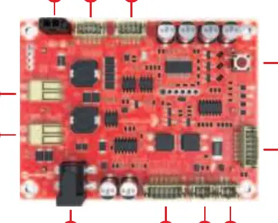
- 12 VDC Power Output (Ports 1, 2, 3): These ports provide 12V DC power to your connected devices.
- Battery Status Button (Port 4): Press this button to check the current charge level of the installed batteries.
- Optional External LED Battery Status and Push Button (Port 5): Allows for remote monitoring of battery status and remote button functionality.
- Optional External LED Charge Done Indicator (Port 6): Provides a visual signal when the battery charging process is complete.
- Optional External LED Power Input Indicator (Port 7): Indicates when power is being supplied to the board.
- Expansion Voltage In/Out Port (Port 8): Used for connecting the optional 325-140 External Power/Charging Board.
- 5 to 24 VDC Input (Ports 9, 10): Main power input ports for charging the batteries.
- 19V Solar Input (Port 11): Dedicated input port specifically for solar panel charging.
Manufacturer information
Dayton Audio
Practical help
Before use
- Ensure 3x18650 lithium batteries are correctly inserted into the board.
- Verify that your power source is within the 5-24V DC range or use a 19V solar panel.
- Confirm that connected devices are compatible with 12V DC output.
- Check all wiring connections to ports 1-3 before applying power.
Specs in practice
- 5 to 24 VDC Input
- The primary voltage range accepted for charging the battery module.
- 19V Solar Input
- A dedicated input port designed to accept power from a 19V solar panel.
- 12 VDC Power Output
- The regulated voltage provided by the board to power external devices.
Images and diagrams
- The board layout includes 11 numbered connection points.
- Ports 1-3 are located at the top for power output.
- Ports 9-11 are located on the left side for power input.
- Port 8 is the expansion port for the 325-140 board.
- Ports 5-7 are for optional external LED indicators.
Model compatibility
- Compatible with the 325-140 External Power/Charging Board via the expansion port (Port 8).

Manual page author
Emily Carter
User documentation editor
Prepares concise manual descriptions and highlights the most useful setup, operation, and maintenance information for readers.