Industrial / Access Control
User Manual for BEA 900 MHz Wireless Transmitters & Receivers
Comprehensive user guide for the BEA 900 MHz Wireless Transmitters & Receivers family. Includes detailed instructions for installation, wiring, DIP switch programming, signal strength testing, battery replacement, and troubleshooting.
Table of contents
Manual images
Click an image to enlargeQuick guide from the manual
This document covers the installation and configuration of the BEA 900 MHz Wireless family. Before beginning, ensure all power to the work area is shut off. When handling circuit boards, dissipate your body's ESD charge to prevent damage. Note that this receiver is not intended for direct use with Maglocks or Electric Strikes; use a Logic Module (e.g., Br3) or Isolation Relay instead. Always remove the plastic pull-tab from the transmitter to enable battery connection.
Receiver and Transmitter Description
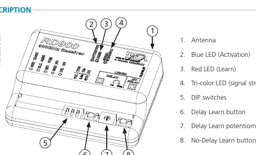
The receiver (RD900) features an antenna, status LEDs (Blue for Activation, Red for Learn, Tri-color for signal strength), DIP switches, and three buttons: Delay Learn, Delay Learn potentiometer, and No-Delay Learn.
Safety and Installation Warnings
- Shut off all power before wiring.
- Maintain a clean, safe environment.
- Do not hold the transmitter button for longer than 5 seconds (Part 15.231 Compliance).
- Ensure compliance with ANSI A156.10/19 standards upon installation.
- Do not attempt internal repairs; contact BEA, Inc. for service.
Wiring Instructions
Receiver Terminals:
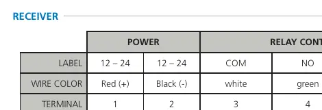
- Terminal 1: Power (Red +)
- Terminal 2: Power (Black -)
- Terminal 3: Relay Common (White)
- Terminal 4: Relay Activation (Green)
- Terminal 5: Not used (Yellow)
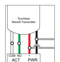
Touchless Retrofit Transmitter: This allows retrofitting existing hard-wired touch plates with touchless plates without running new wires. Connect green/white wires to the touchless plate activation output and parallel the red/black wires with existing in-wall wires for power.
Programming
DIP Switch Settings:
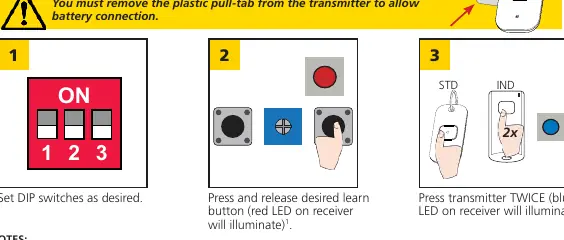
- DIP 1: OFF = Pulse Relay; ON = Toggle Relay.
- DIP 2 (Pulse only): OFF = 0.5 sec Hold Time; ON = 10 sec Hold Time.
- DIP 3: OFF = Standard hold; ON = Extended hold (relay active as long as button is pressed).
Hand-Held Configuration:
- Set DIP switches as desired.
- Press and release the desired learn button on the receiver (Red LED illuminates).
- Press the transmitter button TWICE (Blue LED on receiver illuminates).
Push Plate Configuration: Connect the transmitter (10TD900PB required) to the push plate (NO and COM), install the plate, and follow the Hand-Held Configuration steps.
Signal Strength Indicator
Press and hold the transmitter button (3 seconds for standard, 5 seconds for industrial) to activate the signal strength LED on the receiver: Green (strong), Yellow (medium), Red (weak).
Un-programming
- Single Transmitters: Press BOTH learn buttons until the red LED flashes once (~2s), then press the transmitter button TWICE within 10 seconds.
- All Transmitters: Press BOTH learn buttons until the blue LED illuminates (~10s).
Battery Replacement
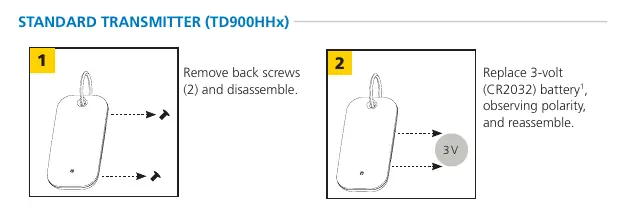
- Standard Transmitter (TD900HHx): Remove back screws, replace with 3-volt CR2032 battery.
- Industrial Transmitter (TD900INDHHx): Remove back screws, replace with two 3-volt CR2032 batteries.
- Push Plate (TD900PB): Replace 2 AAA batteries.
Troubleshooting
If experiencing weak signal, reposition the antenna outside the door header. If the red LED on the receiver is flickering and unable to program, disconnect push plates one by one to identify a stuck plate or faulty transmitter. For constant activation on retrofit units, ensure the transmitter is connected to NO (not NC) and the receiver is set to Pulse Mode.
Technical Specifications
- Frequency: 908 – 918 MHz
- Input Voltage: 12 – 24 VAC / VDC
- Contact Rating: 1.0 A @ 30 VDC; 0.3 A @ 60 VDC; 0.5 A @ 125 VAC
- Operating Temperature: 14 – 131 °F (-10 – 55 °C)
- Transmitter Capacity: 75 (Standard), Unlimited (Universal)
Manufacturer information
BEA Sensors
Practical help
Common problems
Weak signal
Position the receiver antenna outside of the door header.
Red LED on receiver is flickering; unable to program
Disconnect each push plate until the LED stops flickering to identify a stuck plate or faulty transmitter.
No activation (Retrofit)
Verify power and activation wiring at the transmitter, touchless plate, and power source; ensure the receiver is programmed.
Constant activation (Retrofit)
Clear the area in front of the touchless plate; ensure the transmitter is connected to NO (not NC); set receiver/sensor to Pulse Mode.
Before use
- Remove the plastic pull-tab from the transmitter to allow battery connection.
- Shut off all power to the work area before attempting wiring.
- Dissipate body's ESD charge before handling circuit boards.
- Verify compliance with local safety standards (e.g., ANSI A156.10/19) after installation.
- Ensure moving parts will not catch any wires.
Specs in practice
- Input Voltage
- 12 – 24 VAC / VDC
- Contact Rating
- 1.0 A @ 30 VDC; 0.3 A @ 60 VDC; 0.5 A @ 125 VAC
- Operating Temperature
- 14 – 131 °F (-10 – 55 °C)
Images and diagrams
- Receiver terminals: 1-2 (Power), 3 (COM), 4 (NO), 5 (NC).
- DIP Switch 1: Pulse vs Toggle relay.
- DIP Switch 2: 0.5s vs 10s hold time.
- DIP Switch 3: Standard vs Extended hold.
Model compatibility
- Not intended for direct use with Maglocks or Electric Strikes; use a Logic Module (e.g., Br3) or Isolation Relay.

Manual page author
Michael Turner
Technical manual editor
Reviews PDF manuals for structure, safety notes, and practical product details so readers can find the right information quickly.