Tools / Measuring Tools
Dwyer Series 1950G Explosion-Proof Pressure Switch User Manual
Comprehensive installation and operating guide for the Dwyer Series 1950G explosion-proof pressure switch. Includes wiring diagrams, setpoint adjustment procedures, mounting instructions, and technical specifications.
Quick answers from the manual
Quick answer
- The Dwyer Series 1950G is an explosion-proof pressure switch. It must be mounted vertically with the diaphragm in a vertical plane. Electrical connections are made via an internal terminal block, and the setpoint is adjusted using the screw on top of the housing. p. 2
Key actions
- Mounting the switch p. 2
- Adjusting the setpoint p. 2
First start
- Ensure the unit is mounted vertically, connected to the correct pressure source (High/Low ports), and wired according to the terminal block labels (AC or DC). p. 2
Problems and fixes
Switch does not reset properly
Mount with diaphragm in a vertical position.
p. 2
Condensation/deposits
Periodically rotate the vent drain plug.
p. 2Maintenance and reset
- Periodically rotate the vent drain plug to dislodge deposits. p. 2
Technical specifications
| Parameter | Value | Meaning | Pages |
|---|---|---|---|
| Electrical Rating | 10A, 120/240 VAC, 28 VDC | Maximum electrical load capacity. | p. 1 |
| Pressure Limits | 45 in w.c. continuous; 10 psig surge | Maximum pressure the unit can withstand. | p. 1 |
Where to find it in the PDF
- Specifications and Ranges p. 1
- Installation and Maintenance p. 2
Table of contents
Manual images
Click an image to enlargeQuick guide from the manual
The Dwyer Series 1950G is an explosion-proof pressure switch designed for use with air and compatible combustible gases. Key operational requirements include vertical mounting with the diaphragm in a vertical plane to ensure proper resetting. The unit features an internal terminal block for electrical connections and an external adjustment screw for setpoint calibration. Units with the 'NA' suffix are not ATEX compliant and are not intended for use in potentially explosive atmospheres in the EU.
Installation
Mounting: Select a location free from excess vibration and corrosive atmospheres. The switch must be mounted with the diaphragm in a vertical plane and the nameplate in an upright position. Some switches are position-sensitive and may not reset properly if not mounted vertically.
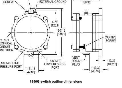
Pressure Connections: Connect the switch to the pressure source using 1/8 inch female NPT ports. Metal tubing with 1/4 inch O.D. is recommended.
- Differential Pressure: Connect the higher pressure source to the port marked HIGH PRESS and the lower pressure source to the port marked LOW PRESS.
- Pressure Only: Connect the pressure source to the HIGH PRESS port; leave the LOW PRESS port open to the atmosphere.
- Vacuum Only: Connect the vacuum source to the LOW PRESS port; leave the HIGH PRESS port open to the atmosphere.
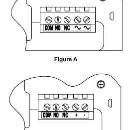
Electrical Connections: Remove the three hex head screws from the cover and loosen the captive screw to swing the cover aside. Connections are made to the internal terminal block.
- AC Supply: Use terminals marked COM, NO, NC, ~, and ~.
- DC Supply: Use terminals marked COM, NO, NC, +, and -.
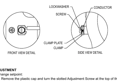
- Grounding: For units with internal and external bonding terminals, use the internal screw for grounding. If an external conductor is required, wrap it a minimum of 180 degrees around the external bonding screw.
Setpoint Adjustment
To change the setpoint:
- Remove the plastic cap covering the adjustment screw.
- Turn the slotted adjustment screw on top of the housing clockwise to raise the setpoint pressure or counter-clockwise to lower it.
- Replace the plastic cap and re-check the setpoint.
For calibration, it is recommended to use a T-assembly with short rubber tubing leads, connecting the switch and a manometer of known accuracy to the pressure source. Apply pressure slowly and ensure the switch is in its final operating position (vertical) during calibration.
Maintenance
The moving parts of the switch require no lubrication. Keep the switch clean. Periodically rotate the vent drain plug and return it to its original position to dislodge deposits that may accumulate due to condensation.
Technical Specifications
- Service: Air and compatible combustible gases.
- Temperature Limits: 0 to 140°F (-17 to 60°C).
- Pressure Limits: 45 in w.c. continuous; 10 psig surge.
- Enclosure Rating: IP54, NEMA 3, 7, and 9.
- Switch Type: 1 Form C relay (SPDT).
- Electrical Rating: 10A, 120/240 VAC, 28 VDC.
- Power Requirements: 24 VDC +/- 10% (120/240 VAC optional).
Manufacturer information
Dwyer Instruments
Practical help
Common problems
Switch does not reset properly
Ensure the switch is mounted with the diaphragm in a vertical position.
Setpoint drift
Note that setpoint drift may occur with ambient temperature changes; re-check calibration if necessary.
Deposits inside switch
Periodically rotate the vent drain plug to dislodge deposits caused by condensation.
Before use
- Verify the model is suitable for the intended hazardous atmosphere (check NA suffix).
- Ensure the mounting location is free from excess vibration and corrosive atmospheres.
- Confirm the ambient temperature is within the -17°C to 60°C range.
- Prepare 1/4 inch O.D. metal tubing for pressure connections.
- Ensure appropriate cable glands (flameproof type) are available for electrical installation.
Specs in practice
- 1 Form C (SPDT)
- Single Pole Double Throw relay configuration.
- IP54, NEMA 3, 7 and 9
- Enclosure ratings indicating protection against dust, rain, and hazardous locations.
- 1/8 inch NPT
- Standard pipe thread size for pressure process connections.
Images and diagrams
- Figure A/B shows the terminal block wiring for AC and DC configurations.
- The outline dimensions diagram illustrates the mounting hole locations and port positions.
- The side view detail shows the proper grounding conductor wrapping (180 degrees).
Model compatibility
- Units with 'NA' suffix are not ATEX compliant and not for use in potentially explosive atmospheres in the EU.
- Compatible with air and non-combustible gases.
- Requires vertical mounting for proper operation.

Manual page author
David Miller
Documentation analyst
Organizes user manual content into clear summaries, with attention to model details, product context, and everyday usability.