Industrial / Pressure Switches
Installation Guide for Danfoss RT Pressure Switches
A comprehensive installation and configuration guide for Danfoss RT series pressure switches. Includes wiring, pressure setting, differential adjustment, and mounting instructions for models RT 19, RT 30, RT 31, RT 32, RT 33, RT 35, and RT...
Quick answers from the manual
Quick answer
- The Danfoss RT pressure switch is installed vertically and requires the assembly of the provided Pg13.5 cable gland to ensure IP66/IP54 protection. Pressure and differential settings are adjusted using the setting knob and differential disc, guided by the nomogram in Fig. 2. p. 1, 2
Key actions
- Mount the pressure switch vertically. p. 1, 2
- Assemble the cable gland. p. 1, 2
- Set pressure and differential. p. 1, 2
Problems and fixes
Pressure connection heating above 100°C
Install a water-filled loop (e.g., 10 mm Cu tube) as a temperature barrier.
p. 1, 2Maintenance and reset
- Manual reset for RT 19B/19S p. 1, 2
Technical specifications
| Parameter | Value | Meaning | Pages |
|---|---|---|---|
| Max. ambient temperature | -40°C – 70°C | Operating temperature range for the environment. | p. 1, 2 |
| Max. medium temperature | 150°C | Maximum temperature of the fluid/gas being measured. | p. 1, 2 |
Where to find it in the PDF
- Installation and Technical Data p. 1, 2
Table of contents
Manual images
Click an image to enlargeQuick guide from the manual
The Danfoss RT series are fail-safe pressure switches designed for industrial and marine applications. Proper installation is critical to ensure the specified IP protection rating and operational reliability. Key steps include mounting the unit vertically, installing the provided cable gland for environmental protection, and using a damping loop or temperature barrier if the medium temperature exceeds 100°C.
Installation
To ensure the correct IP66 (automatic reset) or IP54 (external reset) enclosure rating, the included Pg13.5 cable gland must be assembled correctly. If the gland is not used with a cable, a metal blinding must be installed.
- Mounting: Mount the pressure switch on an upright connector with the unit in a vertical position.
- Pressure Connection: Ensure the pressure inlet is not blocked by impurities.
- Damping: Use a damping loop to mitigate strong pressure pulsations.
- Temperature Barrier: If the medium temperature risks heating the pressure connection above 100°C, install a water-filled loop (e.g., 10 mm Cu tube) to act as a temperature barrier.
- Frost Protection: In water plants, position the switch to avoid exposure to frost.
Setting the pressure switch
The pressure switch must be set to provide the desired function (make or break) on rising or falling pressure, depending on the specific model (e.g., RT 31, RT 32, and RT 33 operate on falling pressure).
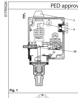
- Pressure Setting: Use the setting knob (5) while reading the main scale (9).
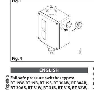
- Differential Setting: Adjust the differential using the differential setting disc (19) in accordance with the nomogram provided in Fig. 2.
Technical data
- Max. ambient temperature: -40°C to 70°C
- Max. medium temperature: 150°C
- Max. test pressure: Varies by model (47 bar for RT 19/32; 25 bar for RT 30A/31; 8 bar for RT 33B/35W/112)
- Min. test pressure: -1 bar
Manufacturer information
Danfoss A/S
Practical help
Common problems
Pressure inlet blockage
Ensure the pressure connection is made so that impurities in the line do not block the inlet; mounting on an upright connector is recommended.
High temperature heating of connection
If the medium temperature exceeds 100°C, install a water-filled loop (e.g., 10 mm Cu tube) as a temperature barrier.
Strong pressure pulsations
Install a damping loop to protect the switch mechanism.
Frost exposure
In water plants, position the switch so it is not exposed to frost; allow it to operate on an air cushion if necessary.
Before use
- Verify the specific model type (e.g., W for automatic reset, B/S for manual reset).
- Ensure the unit is mounted vertically.
- Assemble the Pg13.5 cable gland to maintain IP66/IP54 rating.
- Check the nomogram in Fig. 2 for correct differential settings.
- Ensure the pressure connection is free of impurities.
Specs in practice
- A (Type designation)
- Approved for use in refrigeration plants.
- W (Type designation)
- Pressure monitoring with automatic reset.
- B (Type designation)
- Pressure limiter with external reset.
- S (Type designation)
- Safety pressure limiter with internal reset.
Images and diagrams
- Fig. 1: Overview of the pressure switch components, including setting knob (5) and main scale (9).
- Fig. 2: Nomogram for determining the differential setting.
- Fig. 3: Contact load specifications.
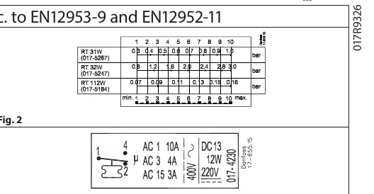
- Fig. 4: Cable gland assembly instructions for IP protection.
- Fig. 5: Dimensions and reset button location.
Model compatibility
- RT 31, RT 32, and RT 33 operate on falling pressure.
- RT 19, RT 30, RT 35, and RT 112 operate on rising pressure.
- Contact load must not exceed AC-3: 2A, 400V and AC-15: 1A, 400V per EN12953-9/EN12952-11.

Manual page author
Emily Carter
User documentation editor
Prepares concise manual descriptions and highlights the most useful setup, operation, and maintenance information for readers.