Industrial / Pressure Switches
Installation Guide for Danfoss KP 17B, KP 17W, and KP 17WB Pressure Switch
Comprehensive installation guide for Danfoss KP 17B, KP 17W, and KP 17WB pressure switches. Includes wiring diagrams, electrical ratings, safety requirements, and pressure adjustment procedures.
Quick answers from the manual
Quick answer
- The Danfoss KP 17B, KP 17W, and KP 17WB are pressure switches for refrigeration systems. Installation requires trained personnel, copper wiring, and adherence to safety standards for flammable refrigerants and electrical grounding. p. 1, 3
Key actions
- Adjustment p. 2
Problems and fixes
Pressure pulsation
Effectively dump pressure pulsations to prevent failure of the bellows.
p. 3Maintenance and reset
- Regularly check the function of the KP switch. p. 3
Technical specifications
| Parameter | Value | Meaning | Pages |
|---|---|---|---|
| LP Range | -0.2 – 7.5 bar | Low pressure operating range | p. 1 |
| HP Range | 8 – 32 bar | High pressure operating range | p. 1 |
| Tightening Torque | 20 lb. in. (2.3 Nm) | Required torque for wiring | p. 2 |
Where to find it in the PDF
- Installation and Specifications p. 1
- Wiring and Adjustment p. 2
- Safety Requirements p. 3
Table of contents
Manual images
Click an image to enlargeQuick guide from the manual
This document provides installation and safety instructions for the Danfoss KP 17B, KP 17W, and KP 17WB pressure switches. These devices are intended for use in refrigeration systems. Key requirements include using copper wire only, ensuring proper electrical grounding, and adhering to strict safety standards regarding flammable refrigerants and mechanical protection.
Technical Specifications
The pressure switches operate within the following ranges:
- LP (Low Pressure): -0.2 to 7.5 bar
- HP (High Pressure): 8 to 32 bar
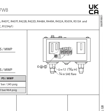
- Refrigerant Compatibility: R22, R134a, R404A, R407A, R407C, R407F, R422B, R422D, R448A, R449A, R452A, R507A, R513A, and selected A2L refrigerants (R455A, R454C, R1234yf).
- Tightening Torque: 20 lb. in. (2.3 Nm).
Installation and Wiring
Caution: Always disconnect the power supply before making wiring connections or performing service to avoid electrical shock. Never touch live parts.
- Use copper wire only for all connections.
- Ensure the installation area is free from high levels of vibration.
- Protect cables from sharp edges and ensure adequate stress relief to prevent pulling forces on the terminals.
- The device must be installed in an area with a low risk of mechanical damage.
Adjustment Procedures
The pressure switches allow for manual adjustment of the cut-in and cut-out points:
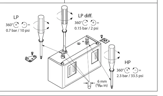
- LP Adjustment: Use the adjustment screw to set the differential and cut-in/cut-out points.
- HP Adjustment: Use the adjustment screw to set the differential and cut-in/cut-out points.
- Refer to the diagrams on page 2 for the specific rotation direction (360° turns) to adjust pressure settings.
Safety Requirements
- Only trained personnel are authorized to handle flammable refrigerant systems and perform installation, maintenance, or exchange of the switch.
- Ensure the system complies with relevant standards such as IEC 60335-2-24, IEC 60335-2-40, IEC 60335-2-89, ISO 5149, or EN378-1.
- Implement electrostatic discharge protection and electrical leakage protection via grounding.
- Regularly check the function of the KP switch.
- In systems with pressure pulsation, ensure effective damping to prevent bellows failure.
Manufacturer information
Danfoss A/S
Practical help
Common problems
Electrical shock hazard
Always disconnect the power supply before wiring or servicing the unit.
Mechanical damage to the switch
Install the switch in an area with low risk of mechanical damage and avoid locations with high vibration.
Cable damage
Ensure cables are not in contact with sharp edges and provide adequate stress relief to prevent pulling forces on terminals.
Before use
- Verify that the refrigerant used is compatible (R22, R134a, A2L, etc.).
- Ensure the system complies with IEC 60335-2-24/40/89 or EN378-1 standards.
- Use copper wire only for electrical connections.
- Ensure the installation environment is free from high vibration.
- Confirm that the installer is trained to handle flammable refrigerant systems.
Specs in practice
- Tightening Torque
- Required torque for connections: 20 lb. in. (2.3 Nm).
Images and diagrams
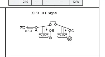
- The wiring diagram shows the connection points for LP and HP signals.
- Adjustment diagrams illustrate how to use a screwdriver to change LP and HP settings (360-degree turns).
- The enclosure diagrams show the difference between IP30 and IP44 protection levels.
Model compatibility
- Compatible with R22, R134a, R404A, R407A, R407C, R407F, R422B, R422D, R448A, R449A, R452A, R507A, R513A.
- Compatible with selected A2L refrigerants: R455A, R454C, R1234yf.

Manual page author
Emily Carter
User documentation editor
Prepares concise manual descriptions and highlights the most useful setup, operation, and maintenance information for readers.