Electronics / Monitors
Dwyer 115T-AV Durablock Air Velocity Gage Instruction Manual
Quick guide for the Dwyer 115T-AV Durablock portable manometer, covering setup, leveling, pressure connections, and air velocity measurement procedures.
Table of contents
Manual images
Jump to the sectionQuick guide from the manual
This document provides operating instructions for the Dwyer 115T-AV Durablock portable manometer. It covers the initial setup, leveling, and specific application procedures for measuring air velocity, static pressure, furnace draft, and air filter pressure drops.
Setup and Operation
- Preparation: Remove the gage from the carrying case.
- Mounting: Set up in a vertical position using the gage stand and leveling screw on a horizontal surface, or use the provided Magneclips for vertical steel surfaces.
- Venting: Turn connectors counter-clockwise 1/2 to 3/4 turns to vent the gage to the atmosphere.
- Leveling: Center the bubble between the crosshairs on the spirit level using the leveling screw or by shifting the gage position.
- Calibration: Slide the scale until the zero mark is directly behind the fluid meniscus. Align the meniscus with its reflected image to eliminate parallax error.
- Fluid: Add or remove gage fluid as necessary.
Pressure Connections
- Plus (above atmospheric) pressure: Use the left-hand gage connection.
- Minus (below atmospheric) pressure: Use the right-hand gage connection.
- Differential pressure: Connect to both sides (e.g., when using a Pitot tube).
Applications
Air Velocity
Connect the manometer differentially to a Pitot tube. Insert the Pitot tube into the duct with the tip directed into the air stream. If the manometer shows a minus indication, reverse the tubes.
Static Pressure
For fan and blower pressures, use the static connection of the Pitot tube or a static pressure tip. For permanent installations, static pressure tips are recommended.
Furnace Draft
Connect the terminal tube to the minus pressure gage opening and insert it into the combustion chamber. For draft loss, connect the manometer differentially to the combustion chamber.
Air Filter Test
Connect the manometer differentially across the filter. Connect the downstream (blower) side to the right-hand (minus) connection and the upstream side to the other connection.
Safety and Maintenance
- Fluid: Use only Dwyer gage fluid.
- Cleaning: Clean with mild soap and water only. Solvents or other cleaning agents may damage the gage.
Manufacturer information
Dwyer Instruments
Practical help
Common problems
Minus indication on manometer during air velocity check
Reverse the tubing connections.
Parallax error during reading
Align the fluid meniscus with its reflected image on the scale.
Inaccurate readings in air velocity tests
Ensure the Pitot tube is centered in the duct and multiply by a factor of 0.9 if a full traverse is not possible.
Before use
- Ensure the gage is in a vertical position.
- Verify the bubble is centered in the spirit level.
- Ensure the zero mark on the scale is aligned with the fluid meniscus.
- Check that connectors are vented to the atmosphere before use.
- Confirm only Dwyer gage fluid is used.
Specs in practice
- Plus connection
- Used for pressures above atmospheric.
- Minus connection
- Used for pressures below atmospheric.
- Differential pressure
- Connection to both sides, used for measuring pressure drop or velocity pressure.
Images and diagrams
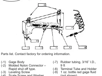
- The gage body features a leveling screw and scale for precise vertical alignment.
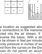
- The Pitot tube must be inserted into the duct with the tip facing the air stream.
- For accurate air velocity, straight duct sections 10 diameters in length are required upstream and downstream.
Model compatibility
- Use only Dwyer gage fluid; other solvents may damage the unit.
- For laboratory accuracy, duct diameter should be 4 inches or greater.
- Static pressure tips are recommended for permanent installations.

Manual page author
David Miller
Documentation analyst
Organizes user manual content into clear summaries, with attention to model details, product context, and everyday usability.