Industrial / Pressure Switches
Installation Guide for Danfoss KP Pressure Switch
Comprehensive installation and configuration guide for Danfoss KP series pressure switches (KP 15, KP 15A, KP 17, KP 47). Includes wiring diagrams, mounting instructions, adjustment procedures, and safety requirements for industrial...
Table of contents
Manual images
Click an image to enlargeQuick guide from the manual
The Danfoss KP pressure switch series is designed for use in refrigeration systems. Before installation, ensure the system complies with relevant safety standards (IEC 60335-2-24, IEC 60335-2-40, IEC 60335-2-89, ISO 5149, EN378-1). Always disconnect the power supply before performing any wiring or service. The device must be installed in an area with low mechanical damage risk and low vibration. Use only copper wire for connections and ensure proper stress relief.
Product Overview and Specifications
The KP series includes models KP 15, KP 15A, KP 17W, KP 17B, KP 17WB, and KP 47WB. These switches are compatible with various refrigerants including R22, R134a, R404A, R407A/C/F, R422B/D, R448A, R449A, R450A, R452A, R507A, R513A, and R717 (KP 15A only). Ambient temperature limits are -40°C (-40°F) for KP 15 and -25°C (-13°F) for KP 17 and KP 47. Maximum ambient temperature is 65°C (149°F).
Mounting and Installation
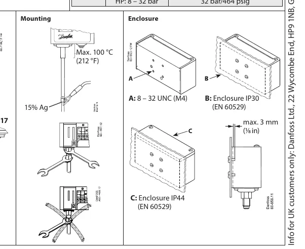
The switches can be mounted in different enclosure configurations (IP30 or IP44). Ensure the mounting surface is stable and free from high vibration. When installing, ensure the cable is not in contact with sharp edges and is secured to prevent pulling forces on the terminals. The maximum temperature for the mounting area is 100°C (212°F).
Electrical Connections
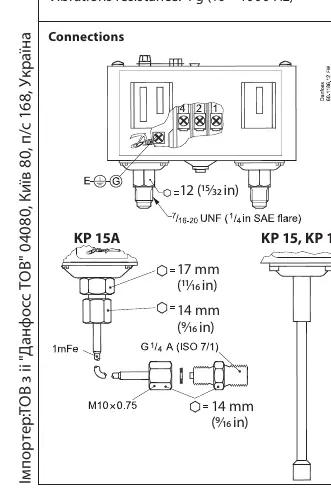
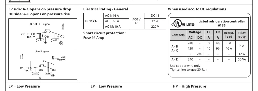
Electrical ratings vary based on the application (AC-3, AC-15). General ratings include 16A at 400V AC. Short circuit protection requires a 16 Amp fuse. Wiring diagrams are provided for SPDT+LP signal and HP signal configurations. Always use copper wire and observe the tightening torque of 20 lb. in.
Adjustment and Reset
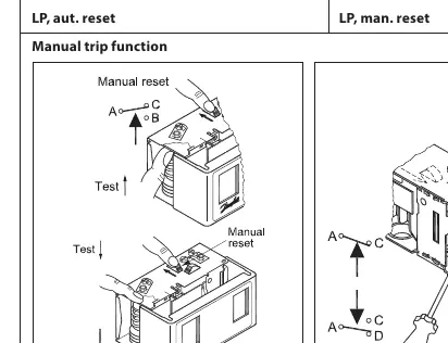
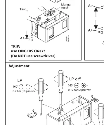
The KP series features adjustable regulation ranges for Low Pressure (LP) and High Pressure (HP). Adjustment screws allow for precise setting of pressure limits. Some models feature convertible reset options (manual or automatic). To change the reset configuration, insert a screwdriver into the slot on the lock disc and turn it to the desired setting. Do not turn the screw on the lock disc itself to avoid damage. A manual trip function is available for testing; use fingers only, do not use a screwdriver.
Safety Requirements
Regularly check the function of the KP switch. If the switch is damaged, the system must be stopped and the switch replaced. Ensure electrostatic discharge protection and electrical leakage protection are implemented. In systems with pressure pulsation, use effective damping to prevent bellows failure. The cycle frequency of the switch should be kept as low as possible.
Manufacturer information
Danfoss A/S
Practical help
Common problems
Switch failure due to vibration
Ensure the switch is installed in an area with low vibration levels as per safety requirements.
Bellows failure
If pressure pulsation is present in the system, install effective damping to protect the bellows.
Electrical shock risk
Always disconnect the power supply before making wiring connections or performing service.
Damage to convertible reset mechanism
Do not turn the screw on the lock disc; only use the slot on the disc to change the reset configuration.
Before use
- Verify refrigerant compatibility with the specific model.
- Check that ambient temperature is within the specified range (-40°C to 65°C).
- Ensure the system complies with IEC 60335 or ISO 5149 standards.
- Confirm electrical supply matches the rated voltage and current (16A max).
- Ensure installation area is free from high vibration and corrosive environments.
Specs in practice
- Regulation range
- The pressure range within which the switch can be adjusted to operate.
- Tightening torque
- The required force (20 lb. in) for securing electrical connections.
Images and diagrams
- Wiring diagrams illustrate SPDT+LP and HP signal connections.
- Adjustment diagrams show the location of LP and HP adjustment screws.
- Reset options diagram displays how to switch between manual and automatic reset modes.
Model compatibility
- Only for use with specified refrigerants; check the Danfoss website for the complete list.
- KP 15A is the only model compatible with R717.
- Not suitable for installation in high-vibration environments.

Manual page author
Michael Turner
Technical manual editor
Reviews PDF manuals for structure, safety notes, and practical product details so readers can find the right information quickly.