Industrial / Pressure Switches
Installation and Operating Instructions for Dwyer Series 2000 Magnehelic Air Filter Gages
A comprehensive guide for the Dwyer Series 2000 Magnehelic Air Filter Gage (Model 2020AV). This manual covers installation procedures, tubing connections, zeroing instructions, and troubleshooting steps to ensure accurate pressure...
Quick answers from the manual
Quick answer
- The Dwyer Series 2000 Magnehelic gage measures pressure drop across air filters. It requires vertical mounting, specific tubing connections to high and low-pressure taps, and must be zeroed before use. p. 1, 2
Key actions
- Zeroing the gage p. 2
- Connecting tubing p. 2
First start
- Perform zero adjustment p. 2
Show 3 more answers Show less
Problems and fixes
Inaccurate readings
Check zero adjustment, tubing tightness, plastic cover seal, and ensure static tips are not plugged or incorrectly oriented.
p. 2Technical specifications
| Parameter | Value | Meaning | Pages |
|---|---|---|---|
| Accuracy | ±2% of full scale | Accuracy throughout range at 70°F. | p. 1 |
| Pressure Limits | -20˝ Hg to 15 psig | Operating pressure range. | p. 1 |
Where to find it in the PDF
- Specifications and Features p. 1
- Installation and Troubleshooting p. 2
Table of contents
Manual images
Click an image to enlargeQuick guide from the manual
The Dwyer Series 2000 Magnehelic gage is designed to measure pressure drop across air filters. Before installation, ensure the gage is mounted vertically. The device requires specific tubing connections to high and low-pressure taps and must be zeroed before initial use. If readings are inaccurate, verify tubing tightness and ensure static pressure tips are correctly positioned in the air stream.
Product Overview
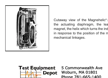
The Magnehelic gage utilizes a molded flexible diaphragm and a magnetic linkage to transmit pressure readings to the pointer, eliminating mechanical linkages. It is designed for use with air and non-combustible, compatible gases.
Installation Procedure
- Prepare the gage: Screw vent valves into the side connections. Ensure back connections are sealed with the provided plugs. Attach the gage to the mounting plate using the three provided 6-32 screws.
- Mounting: Select a location on the filter wall. Drill four 1/8 inch diameter holes for the mounting plate and secure it with the provided self-tapping screws.
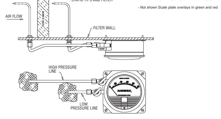
- Static Pressure Tips: Drill two 7/16 inch holes in the duct, one on each side of the filter, at least 12 inches away from the filter. Secure the static pressure tips with the tips directed into the air flow.
- Tubing Connections: Connect 1/4 inch metal tubing from the static pressure tips to the gage. The downstream tip connects to the low-pressure vent valve; the upstream tip connects to the high-pressure vent valve.
- Zeroing: Turn both vent valves to the VENT position. Use the external adjustment screw on the face of the gage to set the pointer to zero. After zeroing, return both valves to the LINE position.
Operation
With vent valves in the LINE position, the gage indicates the pressure drop across the filter. If readings vary significantly from the manufacturer's rating for a clean filter, inspect the system for proper control settings, air balancing, or potential leaks.
Troubleshooting
If initial pressure drop readings do not agree with the filter manufacturer's specifications, perform the following checks:
- Verify the zero adjustment.
- Check all tubing connections for tightness.
- Ensure the plastic cover is securely in place and air-tight.
- Confirm that static pressure tips or fittings are not plugged.
- Ensure static pressure tips point directly into the air stream to avoid velocity pressure errors.
Specifications
- Service: Air and non-combustible, compatible gases.
- Accuracy: Plus or minus 2 percent of full scale (plus or minus 3 percent on -0 and plus or minus 4 percent on -00 ranges).
- Pressure Limits: -20 inches Hg to 15 psig.
- Temperature Limits: 20 to 140 degrees Fahrenheit.
- Process Connections: 1/8 inch female NPT duplicate high and low pressure taps.
Manufacturer information
Dwyer Instruments
Practical help
Common problems
Pressure readings do not match manufacturer specifications
Check zero adjustment, ensure tubing connections are tight, verify the plastic cover is air-tight, and confirm static pressure tips are not plugged.
Velocity pressure error
Ensure static pressure tips are pointed directly into the air stream.
Before use
- Ensure the gage is mounted in a vertical position.
- Verify that back connections are sealed with the provided plugs.
- Ensure vent valves are in the LINE position for operation.
- Confirm static pressure tips are installed at least 12 inches from the filter.
- Perform zero adjustment before putting the gage into service.
Show more Show less
Specs in practice
- Pressure Limits
- Operating range from -20 inches Hg to 15 psig.
- Temperature Limits
- Operating temperature range is 20 to 140 degrees Fahrenheit.
Images and diagrams
- The installation diagram illustrates the correct placement of static pressure tips in the duct, maintaining a 12-inch distance from the filter, and the routing of tubing to the high and low-pressure connections on the gage.
Model compatibility
- Designed for air and non-combustible, compatible gases.
- Consult factory for other mounting orientations besides vertical.

Manual page author
Emily Carter
User documentation editor