HVAC / Condensate Pumps
Quick Start Guide for Sauermann CP 210-R Differential Pressure Transmitter
Quick start guide for the Sauermann CP 210-R differential pressure, air velocity, and temperature transmitter. Includes installation, wiring diagrams, DIP switch configuration, autozero procedures, and technical specifications.
Quick answers from the manual
Quick answer
- The CP 210-R is a differential pressure and temperature transmitter. It requires a qualified technician for installation, supports multiple power supply options (24V or 100-240V), and allows output signal configuration via internal DIP switches. p. 2
Key actions
- Mounting the transmitter p. 2
- Performing an autozero p. 2
First start
- Verify power supply type on the label before connecting. p. 2
Show 3 more answers Show less
Maintenance and reset
- Perform autozero to guarantee correct working. p. 2
Technical specifications
| Parameter | Value | Meaning | Pages |
|---|---|---|---|
| Power Supply | 24 Vac/Vdc or 100-240 Vac | Input voltage requirements | p. 2 |
| Protection | IP65 | Ingress protection rating | p. 2 |
Where to find it in the PDF
- Quick Start Guide p. 1, 2
Table of contents
Manual images
Click an image to enlargeQuick guide from the manual
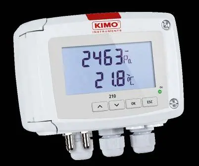
The Sauermann CP 210-R is a transmitter designed for measuring differential pressure, air velocity, air flow, and temperature. This guide provides essential information for installation, electrical connection, and device configuration. Always ensure the device is installed by a qualified technician and that the power supply matches the specifications on the device label.
General features
The device features two 4-wire analogue outputs (0-5/10 V or 0/4-20 mA) and two relay outputs. It is protected by an IP65 housing and operates in environments from -10 to +50 degrees Celsius. It supports manual autozero via a push-button and automatic autozero on specific models (CP211/212).
Mounting
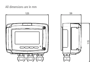
To mount the transmitter, fix the ABS plate to the wall using the supplied screws and pins (drilling diameter 6 mm). Insert the transmitter into the fixing plate at a 30-degree angle and rotate the housing clockwise until you hear a click, confirming it is securely installed.

Connections
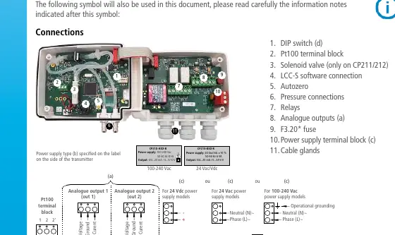
Electrical connections must be made while the device is powered off. Verify the power supply type (24 Vac/Vdc or 100-240 Vac) on the side label before connecting. The device requires a switch and circuit breaker upstream. For 100-240 Vac models, use delayed-action fuses to handle current surges during startup.
Configuration
The output signal (voltage or current) is configured using the DIP switches on the electronic board. Refer to the configuration table in the manual to set the switches for 4-20 mA, 0-20 mA, 0-10 V, or 0-5 V outputs. Advanced configuration of units, ranges, and calculation functions can be performed via the keypad (on display models) or optional LCC-S software.
Autozero
To perform an autozero, unplug the two pressure connection tubes and press the Autozero key. On CP211 and CP212 models, unplugging the tubes is not necessary. A successful autozero is indicated by the green On light cycling off and on, and the display showing autoZ.
Maintenance
Avoid using aggressive solvents for cleaning. Protect the transmitter and probes from cleaning products containing formalin, which may be used in ducts or rooms.
Manufacturer information
Sauermann
Practical help
Common problems
Device does not power on
Verify the power supply voltage matches the label on the side of the transmitter (24V vs 100-240V).
Incorrect output signal
Check the DIP switch configuration on the electronic board against the table provided in the manual.
Measurement drift
Perform an autozero procedure to recalibrate the sensor.
Before use
- Verify power supply type (24 Vac/Vdc or 100-240 Vac) on the device label.
- Ensure installation is performed by a qualified technician.
- Install a switch and circuit breaker upstream of the device.
- Ensure the environment is non-condensing and within -10 to +50 degrees Celsius.
- For 100-240 Vac models, use delayed-action fuses.
Show more Show less
Images and diagrams
- Wiring diagram: Shows terminal block connections for power supply, relays, and analogue outputs.
- DIP switch table: Defines the switch positions required to select between 4-20 mA, 0-20 mA, 0-10 V, and 0-5 V output modes.
Model compatibility
- Compatible with air and neutral gases.
- Operating altitude up to 2000 meters.

Manual page author
David Miller
Documentation analyst