Industrial / Electrical
Operating Instructions for S+S Regeltechnik PREMASGARD 211x / 212x / 212x-SD Pressure Transducers
Quick guide for S+S Regeltechnik PREMASGARD 211x, 212x, and 212x-SD pressure transducers. Includes installation, wiring, DIP switch configuration, and calibration procedures.
Quick answers from the manual
Quick answer
- The PREMASGARD 211x/212x series are pressure and differential pressure transducers with 8 switchable measuring ranges and 2 switchable output signals (0-10V/4-20mA). p. 3
Key actions
- Mounting p. 5, 9
- Calibration p. 7
First start
- Ensure 24V AC/DC power, connect pressure hoses to P+ and P-, and configure DIP switches. p. 6, 9
Show 4 more answers Show less
Problems and fixes
Zero point calibration
Press 'key' for 5 seconds after 60 minutes of operation.
p. 7Maintenance and reset
- Perform automatic zero point calibration using the 'key' button. p. 7
Technical specifications
| Parameter | Value | Meaning | Pages |
|---|---|---|---|
| Power supply | 24V AC/DC | Operating voltage | p. 3 |
| Output | 0-10V / 4-20mA | Switchable output signal | p. 3 |
| Protection | IP67 / IP54 | Protection type | p. 3 |
Where to find it in the PDF
- Technical Data p. 3
- Mounting Diagrams p. 5
- DIP Switch Settings p. 6
- Calibration p. 7
Table of contents
Manual images
Click an image to enlargeQuick guide from the manual
The PREMASGARD 211x/212x series are pressure and differential pressure transducers designed for clean air and non-aggressive gases. Important: Before performing zero point calibration, the device must be in operation for at least 60 minutes. Ensure correct wiring polarity to avoid short circuits. The device is factory-calibrated, but manual adjustment is recommended during commissioning if operating conditions deviate from standard.
Product description
These compact pressure sensors feature 8 switchable measuring ranges and 2 switchable output signals (0-10V or 4-20mA). They are used for monitoring pressure in ventilation, air conditioning, clean rooms, and filter technology. The piezo-resistive element provides high accuracy and temperature compensation.
Installation and mounting
The device can be mounted in any position. Ensure that cables do not go under the board to prevent damage to hose connections. The pressure inputs are marked P1 (+) for higher pressure and P2 (-) for lower pressure. Four types of monitoring are supported:
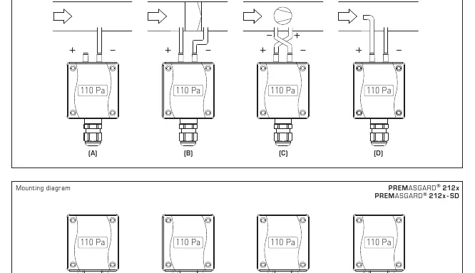
- Below-atmospheric pressure: P1 open to atmosphere, P2 connected to duct.
- Filter: P1 upstream, P2 downstream.
- Ventilator: P1 downstream, P2 upstream.
- Volume flow: P1 dynamic pressure, P2 static pressure.
Configuration via DIP switches
The device settings are configured using DIP switches:
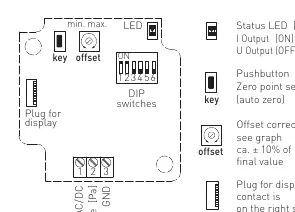
- DIP 1 & 2: Pressure range selection (8 ranges available).
- DIP 3: Measuring range mode (Unidirectional or Bidirectional).
- DIP 4: Output characteristic (Linear or Square root extracting).
- DIP 5: Signal filtering (1s or 10s).
- DIP 6: Output type (Voltage 0-10V or Current 4-20mA).
Calibration
Automatic zero point calibration: Connect P(+) and P(-) with a hose (0 Pa difference). Press the 'key' (auto zero) button for 5 seconds. A LED will signal the calibration process. Completion is confirmed by a steady LED light and the display changing from 'AUTO 0' to 'PROG 0'.
Manual offset adjustment: Use the potentiometer on the circuit board to adjust the offset by ± 10% of the pressure range. This requires a 2.5mm screwdriver.
Technical data
- Power supply: 24V AC/DC (± 10%)
- Output: Switchable 0-10V / 4-20mA
- Protection: IP67 (211x/212x) or IP54 (212x-SD)
- Media: Clean air and non-aggressive, non-combustible gases
- Temperature range: -20 to +50 °C
Manufacturer information
S+S Regeltechnik GmbH
Practical help
Common problems
Output signal incorrect
Verify DIP switch settings (DIP 4, 6) and ensure wiring polarity is correct.
Zero point drift
Perform automatic zero point calibration after 60 minutes of operation.
Device damaged
Ensure no overvoltage is applied to the output; the voltage output is short-circuit proof but not overvoltage proof.
Before use
- Ensure power supply is 24V AC/DC
- Verify pressure range requirements
- Check wiring polarity
- Ensure installation environment is free from heat sources
- Allow 60 minutes warm-up before calibration
Show more Show less
Specs in practice
- Measuring ranges
- 8 switchable ranges via DIP switches 1 and 2.
Images and diagrams
- Mounting diagrams show connection for below-atmospheric, filter, ventilator, and volume flow monitoring.
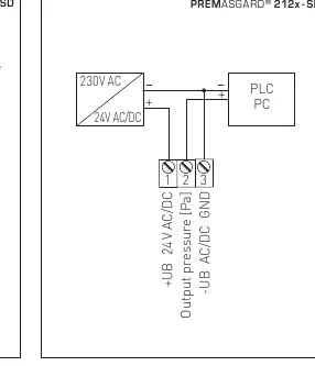
- Wiring diagrams show individual and parallel operation schemes.
- DIP switch diagram details settings for range, mode, and output.
Model compatibility
- Compatible with clean air and non-aggressive, non-combustible gases.
- Not for use in safety-relevant applications like EMERGENCY STOP.

Manual page author
Michael Turner
Technical manual editor