Industrial / Motor Drives
Vent-Axia 1.5A Electronic Single Phase Speed Controller Installation and Wiring Instructions
Quick guide for the Vent-Axia 1.5A Electronic Single Phase Speed Controller. Includes essential installation, wiring, mounting, and minimum speed adjustment procedures.
Table of contents
Manual images
Click an image to enlargeImportant Safety Information
Before installing or using the controller, please read these instructions carefully. This equipment must be earthed. The mains supply must be isolated before making any connections. All wiring must be in accordance with BS 7671:1992, current I.E.E wiring regulations, local building, and factory regulations in your country.
Mounting
The controller may be sited in any convenient position that is unaffected by direct heat sources such as radiators or boilers. Ensure the controller is installed in a ventilated area and that the enclosure is securely mounted using appropriate fixing screws or bolts. If the enclosure is mounted on a metal surface or partition, ensure that the surface is earthed.
Wiring Instructions
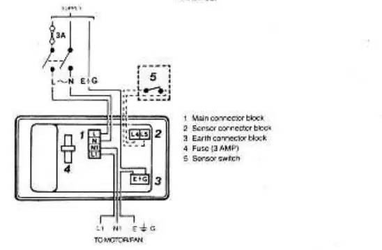
The installation must be provided with a double-pole isolator switch having a contact separation of not less than 3mm and must be protected with a 3 amp fuse. Ensure that the mains supply is isolated before proceeding. Remove the lid and connect the unit in accordance with the provided wiring diagrams. When using surface wiring that is not contained in conduit, the supply and output cables must be securely clipped to the mounting surface close to the controller.
Minimum Speed Adjustment
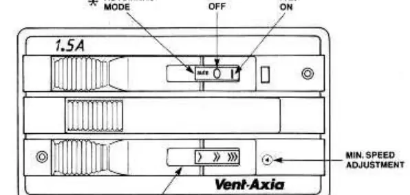
The control unit is factory set to Vent-Axia's recommended minimum speed. A minimum speed adjuster is located on the front of the controller and is exposed when the bottom slide bar is moved fully to the left. Using a small screwdriver, turn the adjuster clockwise to increase the minimum speed setting. After any adjustment, ensure the fan starts from a stationary condition by using the ON/OFF switch with the variable speed slide knob set fully to the left.
Notes on Running
Before switching on, check that the control unit and motor/fan are secure and that earth connections have been made. Switch on the mains and slide the control to maximum and down to minimum to ensure the motor/fan operates accordingly. If using automatic control via an electromechanical ON/OFF switched sensor (e.g., thermostat, timer, relay), ensure the sensor switch is adequately rated for the switched load.
Practical help
Common problems
Fan does not start
Check that the mains supply is on, the 3A fuse is intact, and all wiring connections are secure.
Fan speed too low at minimum setting
Use a small screwdriver to turn the minimum speed adjuster on the front of the controller clockwise to increase the minimum speed.
Before use
- Ensure mains supply is isolated before starting installation
- Verify the installation location is ventilated and away from heat sources
- Confirm a double-pole isolator switch is installed
- Ensure a 3A fuse is used for protection
- Verify that the unit and mounting surface are properly earthed
Images and diagrams
- The unit diagram shows the variable fan speed slide control and the location of the minimum speed adjuster.
- The wiring diagram illustrates the connections for the main connector block, sensor connector block, earth connector block, fuse, and sensor switch.
Model compatibility
- Only mechanical or electro-mechanical switched sensors should be used for automatic switching.
- Sensors must be rated at 1.5A inductive 220-240V AC.

Manual page author
Emily Carter
User documentation editor
Prepares concise manual descriptions and highlights the most useful setup, operation, and maintenance information for readers.