Home / Security
User Guide for Lexium 17D HP Series Servo Drive
Comprehensive user guide for the Lexium 17D HP series servo drive. Includes installation, wiring diagrams, system operation, troubleshooting, and technical specifications.
Table of contents
Manual images
Click an image to enlargeQuick guide from the manual
This guide provides essential information for the installation, operation, and maintenance of the Lexium 17D HP series servo drive. Always ensure that all safety regulations are followed. Before performing any maintenance, wait at least five minutes after disconnecting the power to allow the DC link capacitors to discharge below 40V.
Safety Precautions
DANGER: Electric shock hazard. Keep all covers and cabinet doors closed during operation. Never disconnect electrical connections while power is applied. Lethal voltages up to 900V can be present. Always measure the voltage in the DC Link circuit before touching any components.
WARNING: Thermal hazard. The front panel acts as a heat sink and can reach temperatures above 80°C. Wait until it cools below 40°C before touching.
Product Overview
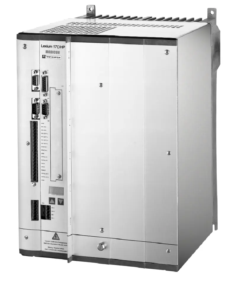
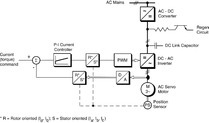
The Lexium 17D HP series consists of a three-phase brushless servo amplifier, power supply, and high-performance digital controller. The family includes two models based on output current: 112A (MHDA1112) and 198A (MHDA1198). These drives are intended for use with Lexium BPH series brushless servo motors.
Wiring and I/O
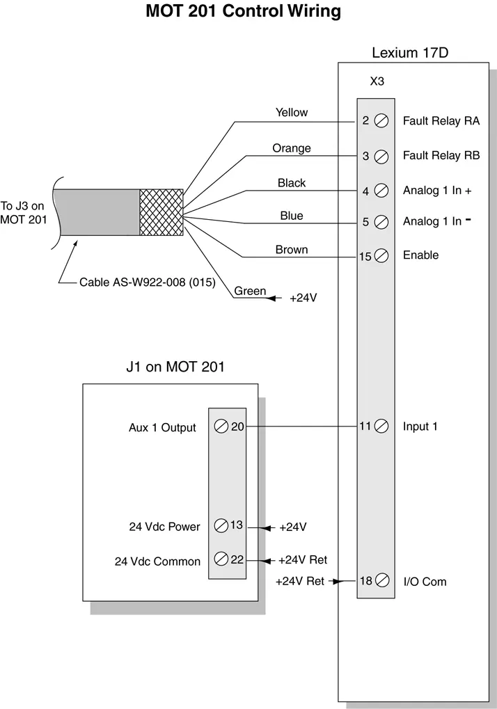
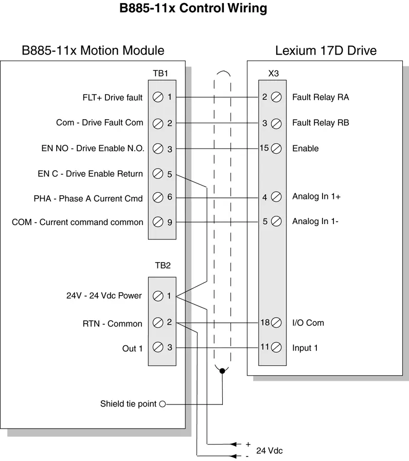
Proper wiring is critical for system performance. Power and control cables must be routed separately with a minimum separation of 20 cm. The drive requires a 24 Vdc bias power supply. The X3 connector handles analog/digital I/O, while X6 is used for RS-232 communication. Shielded cables are mandatory for signal integrity.
System Operation
The drive features a restart lock (-AS-) function designed to prevent accidental system restarts. This function must be used in accordance with safety standards (EN60204, EN292, EN954-1). The drive can be tuned using the UniLink commissioning software, which allows for parameter configuration and oscilloscope tuning.
Troubleshooting
The drive displays status, warning, and error codes on its front panel LED display. Non-fatal faults generate warnings (n-codes), while fatal faults generate errors (F-codes). Common issues include communication errors, motor rotation failures, and motor oscillations. Always check cable connections and parameter settings before contacting support.
Specifications
The drive operates on a three-phase system ranging from 208V to 480V. It supports various feedback devices, including resolvers and Sin-Cos encoders. Detailed electrical, environmental, and mechanical specifications are provided in the full manual, including wire size recommendations for AC mains, DC link, and signal connections.
Manufacturer information
Schneider Electric
Practical help
Common problems
No communication with PC
Check if the correct cable is used, ensure the cable is plugged into the correct port, and verify the correct PC interface is selected in the software.
Motor does not rotate
Ensure the drive is enabled, check for breaks in the analog input cable, verify motor phases, ensure the brake is released, and check if the motor is mechanically blocked.
Motor oscillates
Reduce the Kp (speed controller) gain, check for breaks in the feedback cable shielding, and ensure Analog Com is connected to the controller common.
Before use
- Ensure the drive is mounted in an appropriately vented and closed cabinet.
- Verify that all wiring complies with the National Electrical Code (NEC) or local equivalent.
- Ensure the drive and motor are properly connected to earth.
- Check that the mains supply voltage matches the drive specifications.
- Ensure the 24 Vdc bias supply is connected and isolated.
- Verify that all safety interlocks and emergency stop switches are installed.
Images and diagrams
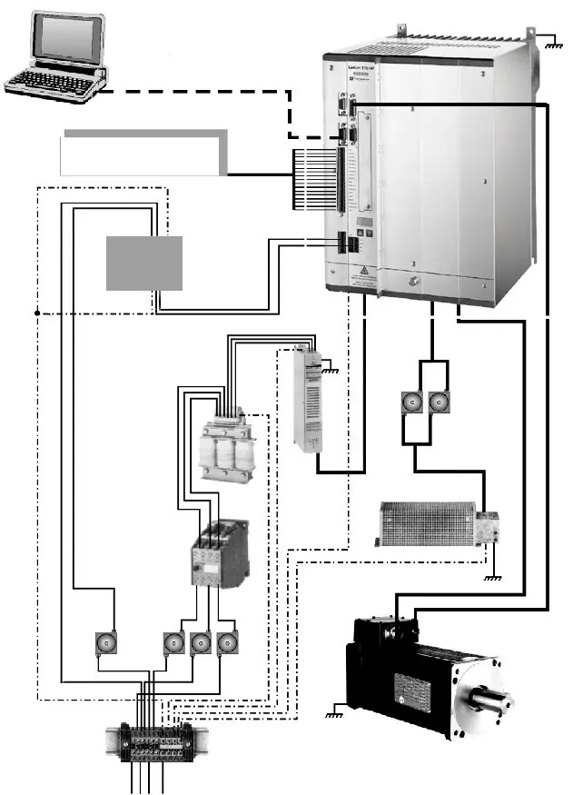
- The system configuration diagram illustrates the connections between the drive, PC, PLC, mains filter, choke, fuses, and motor.
- Wiring diagrams are provided for various motion controllers, including MOT 201, Quantum 140 MSx, and Premium CAY modules.
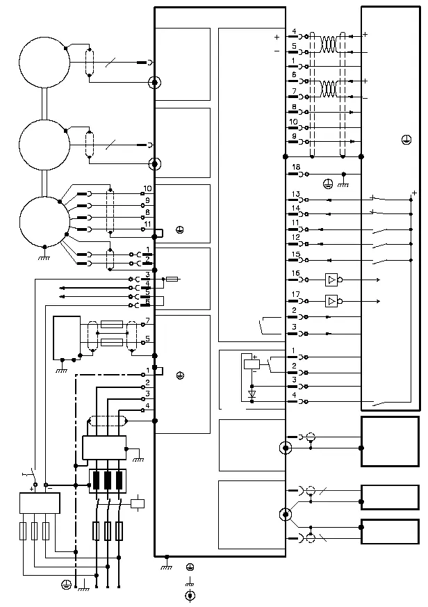
- Specific diagrams detail the wiring for resolvers, encoders, and the restart lock (-AS-) safety circuit.
Model compatibility
- The Lexium 17D HP drive is designed to drive Lexium BPH series brushless servo motors.
- Compatible motion modules include Quantum 140 MSx, Compact MOT 201, B885-11x, and Premium CAY.

Manual page author
David Miller
Documentation analyst
Organizes user manual content into clear summaries, with attention to model details, product context, and everyday usability.