HVAC / Thermostats & Controls
Start-Up and Service Instructions for Carrier 19XRV and 23XRV Chiller VFD
Comprehensive start-up and service guide for Carrier 19XRV and 23XRV chillers equipped with Eaton LCX9000 VFD. Includes installation, configuration, troubleshooting, and maintenance procedures.
Table of contents
Manual images
Click an image to enlargeQuick guide from the manual
This manual provides essential start-up and service instructions for the Eaton LCX9000 VFD used with Carrier 19XRV and 23XRV chillers. Key procedures include safety precautions, drive commissioning, troubleshooting fault codes, and drive removal. Always ensure power is disconnected and capacitors are discharged before performing any service.
Safety Considerations
DANGER: High voltage is present on motor leads even when the motor is not running. Always open the power supply disconnect before touching motor leads or terminals. DC bus capacitors retain hazardous voltages after input power is disconnected; wait five minutes after power-down before touching internal components.
WARNING: Do not use a torch to remove components as the system contains oil and refrigerant under pressure. Use protective gloves and goggles. Ensure adequate ventilation and follow ANSI/ASHRAE 15 standards.
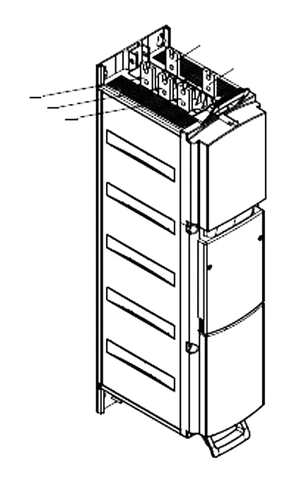
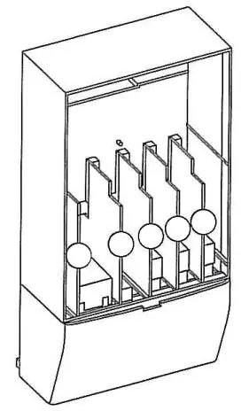
Identifying Drive Components
The drive is categorized by frame size (CH63, CH72, CH74). Refer to the nameplate on the control panel for specific model and electrical data. DC bus terminals are located on the input end of the drive modules.
Start-Up and Commissioning
Initial start-up must be performed by a technician certified by Eaton and Carrier. The commissioning process includes:
- Allowing 24 hours for room temperature stabilization if the chiller was stored outdoors.
- Entering parameters in the VFD_CONF screen.
- Installing surge suppression devices if required.
- Reviewing power wiring and grounding.
- Visually examining the drive enclosure for corrosion, moisture, or debris.
- Measuring and recording incoming line voltages (Vab, Vbc, Vca).
Troubleshooting
The drive displays Alert and Alarm codes on the ICVC. An Alert is a warning message, while an Alarm indicates a failure resulting in a shutdown. Fault codes can be identified using the Eaton code in the VFD_HIST screen. Common faults include Overcurrent, Overvoltage, Ground Fault, and Drive Overtemperature.
Removing the Drive from the Enclosure
When removing the drive, consider the weight (CH72: 198 lb, CH63: 264 lb, CH74: 617 lb). Use properly rated lifting equipment. Disconnect all power cabling, refrigerant cooling lines, and mounting bolts before lifting. Reinstall by reversing the removal procedure.
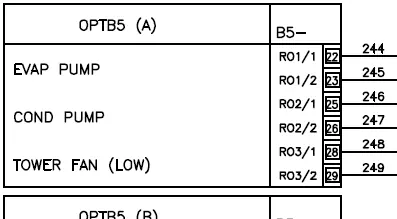
Wiring and Connections
Refer to the wiring schematics in Appendix A for detailed connection diagrams, including control panel terminals, oil pump terminals, and power panel connections.
Manufacturer information
Carrier Global Corporation
Practical help
Common problems
Overcurrent
Check for sudden heavy load increase, short circuit in motor cables, or unsuitable motor.
Overvoltage
Set deceleration time longer; add brake chopper or brake resistor.
Ground Fault
Check motor cables and motor for insulation failure or grounded condition.
Drive Overtemperature
Check coolant flow and temperature; ensure air circulation is not blocked.
Under-voltage
Check supply voltage; reset fault and restart.
Before use
- Verify job information (Name, Number, City, State, Zip).
- Record VFD serial and part number from nameplate.
- Record chiller serial, model, and motor electrical data from machine nameplate.
- Ensure chiller has stabilized at room temperature for 24 hours if stored outdoors.
- Verify power wiring and grounding connections.
- Check inside of drive enclosure for corrosion, moisture, or debris.
- Measure and record incoming line voltages.
Specs in practice
- Frame Size (CH63, CH72, CH74)
- Determines the physical size, weight, and component configuration of the VFD.
- Voltage Imbalance
- Must be 2% or less for proper operation.
- DC Bus Voltage
- Retains hazardous voltage; must be verified as 0V before servicing.
Images and diagrams
- Fig. 1A/1B: DC Bus location for different frame sizes.
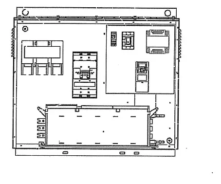
- Fig. 3: Eaton LCX9000 Frame Sizes and control box layout.
- Fig. 5: Configuration Jumper settings.
- Fig. 8A/8B/9: Procedures for removing the drive from the enclosure.
- Appendix A: Detailed wiring schematics for 19XRV and 23XRV.
Model compatibility
- Requires Eaton LCX9000 VFD.
- Compatible with Carrier 19XRV and 23XRV chillers with PIC III controls.
- Terminal lugs are suitable for copper wire only.

Manual page author
David Miller
Documentation analyst
Organizes user manual content into clear summaries, with attention to model details, product context, and everyday usability.