Industrial / Motor Drives
User Manual for Welldana iSAVERX 1100/1100C Frequency Inverter
Quick guide for the Welldana iSAVERX 1100 and 1100C frequency inverter. Includes installation steps, wiring diagrams, control panel operation, timer settings, and error code troubleshooting.
Table of contents
Manual images
Click an image to enlargeQuick Guide
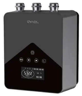
The Welldana iSAVERX 1100/1100C is an energy-saving frequency inverter designed for swimming pool pumps. Before installation, ensure your pump is compatible (permanent split capacitor motor only). The device features three operation modes (Night, Day, Backwash) and allows for up to 4 timer settings to optimize energy usage. Always ensure proper ventilation and grounding during installation.
Safety Instructions
To prevent fire, electrical shock, or serious injury, read the manual carefully. The device must be used with an RCD with a rated residual current not exceeding 30mA. Do not touch the heat sink during operation or for 30 minutes after switching off.
Incompatible Motors:
- Single (Three) phase motors with centrifugal switch
- Pool pump motors with start relays or switches
- Series or DC motors
- Motors with faults in rotors or capacitors
- Shaded-pole asynchronous motors
Technical Data
Both models operate on 1 phase AC 220-240V, 50Hz, with a speed range of 1200-2900 rpm. The iSAVERX 1100 is for single-phase pumps (max 6A), while the iSAVERX 1100C is for three-phase pumps (max 4.5A). Both provide a maximum output power of 1.1kW.
Installation
Choose a location with an ambient temperature between -10°C and 40°C, 45-90% relative humidity, and good ventilation. Ensure a minimum clearance of 40cm on the sides and 25cm at the bottom for cooling. Do not install in enclosed spaces with limited airflow.
Connecting to Pool Pump
Follow these steps for correct wiring:
- Turn off all electrical supply to the pool pump.
- Plug the pool pump into the device outlet marked PUMP CONNECTION ONLY.
- Plug the device into the main switch/chlorinator/timer connection.
- Connect the grounding wire on the device to the ground terminal of the pool pump motor.
- Switch power back on and ensure the chlorinator/timer is active.
Settings & Operation
The control panel allows you to manage speed and timers. Upon startup, the pump runs at 2900 rpm for one-minute self-priming. You can adjust the speed using the arrow buttons. The device features three modes: Night (Low, 1200-1650 rpm), Day (Medium, 1700-2400 rpm), and Backwash (High, 2450-2900 rpm).
Timer Setting
You can set up to 4 timers to run the pump at different speeds. Press the timer button to enter settings, use arrows to set the time, and select the speed range. Hold the timer button for 3 seconds to save settings.
External Control
External control is optional and can be enabled via specific pins (1-7). Do not apply voltage to these inputs. Connecting specific pins to COM allows for external speed control or stopping the device.
Parameter Setting
Under OFF mode, hold the arrow buttons for 3 seconds to enter parameter settings. You can adjust priming time (0-10 min), minimum RPM, and specific speeds for PIN1, PIN2, and PIN3.
Protection & Error Codes
The device includes self-protection features. If an error code appears (e.g., E001, E002, E101), refer to the error table. AL01 indicates auto speed reduction due to high temperature; the device will resume normal operation once the temperature drops.
Disposal
Dispose of the product at a designated collection point for recycling waste electrical and electronic equipment.
Practical help
Common problems
E001: Abnormal input voltage
Not faulty; check power supply stability.
E002: Output over current
Not faulty; check pump load.
E101: Heat sink over heat
Contact your supplier.
AL01: Auto speed reduction
Automatic protection against high temperature; will resume when temperature drops to 68°C.
Before use
- Verify pool pump has a permanent split capacitor motor.
- Ensure RCD with max 30mA is installed.
- Check for damage before installation.
- Ensure ambient temperature is between -10°C and 40°C.
- Provide minimum clearance (40cm side, 25cm bottom) for ventilation.
- Ensure total length of output cable and pump cable does not exceed 2m.
Specs in practice
- Input Voltage
- 220-240V, 1 phase AC.
- Output Power
- Max 1.1kW.
Images and diagrams
- Fig. 2: Installation clearance requirements.
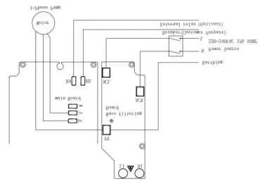
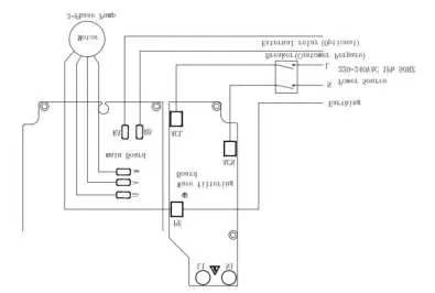
- Fig. 4: Cable connection diagram for pool pump.
- Fig. 6: 1-ph pump connection diagram.
- Fig. 7: 3-ph pump connection diagram.
Model compatibility
- Only compatible with permanent split capacitor motors.
- Not compatible with motors with centrifugal switches, start relays, DC motors, or shaded-pole asynchronous motors.

Manual page author
David Miller
Documentation analyst
Organizes user manual content into clear summaries, with attention to model details, product context, and everyday usability.