Industrial / Electrical
Installation and User Guide for ELKO USB PD A+C Charger 21W
A comprehensive installation and user guide for the ELKO USB PD A+C Charger 21W. Includes wiring instructions, technical specifications, safety warnings, and installation requirements for qualified professionals.
PDF source: NO · summary: English
Quick answers from the manual
Quick answer
- This device is a USB PD A+C Charger (21W) designed for fixed electrical installation. It must be installed by a qualified professional and requires a compatible frame to complete the assembly. p. 1, 2
Key actions
- Connect earth wires (PE) using a junction block to maintain continuity. p. 1, 2
- Disconnect the device from the circuit during insulation resistance tests. p. 1, 2
Problems and fixes
Equipment damage during insulation test
Ensure the device is disconnected from the circuit (L and N) before testing.
p. 1, 2Show 2 more answers Show less
Technical specifications
| Parameter | Value | Meaning | Pages |
|---|---|---|---|
| Input Voltage | 220-240 V~, 50/60 Hz | Standard mains power requirement | p. 1, 2 |
| Max Output Power | 21 W | Maximum combined power output | p. 1, 2 |
Where to find it in the PDF
- Installation and Technical Data p. 1, 2
Table of contents
Manual images
Click an image to enlargeQuick Guide for Installation
This document provides essential installation and technical information for the ELKO USB PD A+C Charger. Important: Electrical installation must only be performed by skilled professionals with knowledge of installation networks, electrical devices, and safety standards. Failure to follow these instructions can result in death, serious injury, or equipment damage.
Installation and Wiring
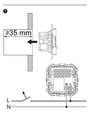
When installing the USB charger insert to replace an existing socket-outlet, you must connect the earth wires (PE) together using a junction block to maintain earth line continuity for all socket outlets in the circuit.
- Wire Stripping: Strip wires to a length of 7-9 mm.
- Wire Size: Compatible with 2 x 1.5 mm² to 2 x 2.5 mm² wires.
- Torque: Tighten terminal screws to 0.5 Nm.
- Wiring: Connect Line (L) and Neutral (N) as indicated in the device diagram.
- Accessories: The device must be completed with a frame in a corresponding design and color.
Technical Specifications
The charger supports Power Delivery (PD) 3.1 with PPS and other modes.
- Input Voltage: 220-240 V~, 50/60 Hz
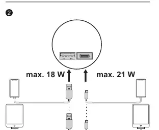
- USB-C Output: 5.0 V/3.0 A (15.0 W), 9.0 V/2.33 A (21.0 W), 12.0 V/1.75 A (21.0 W), 5.0-12.0 V (Max 21.0 W)
- USB-A Output: 5.0 V/3.0 A (15.0 W), 9.0 V/2.0 A (18.0 W), 12.0 V/1.5 A (18.0 W)
- Combined Output (A+C): Max 5.0 V/3.4 A (17.0 W), max 2.4 A per port.
- Protection: Output over-current, over-voltage, short circuit, and over-temperature protection with automatic power adjustment.
- Efficiency: Average active efficiency > 86.2%; Low load (10%) efficiency > 76.2%.
- Standby Consumption:< 0.05 W.
Safety and Maintenance
Ensure the device is disconnected from the circuit (L and N) during any insulation resistance testing to prevent equipment damage. Use only original or specified USB-C cables to ensure charging compatibility. Dispose of the device separately from household waste at an official collection point.
Manufacturer information
ELKO AS
Practical help
Common problems
Device not charging or slow charging
Ensure you are using an original USB-C cable or a cable specifically certified for the required charging protocol.
Earth continuity issues after installation
If replacing a socket, you must connect the earth wires (PE) together using a junction block to maintain continuity for the entire circuit.
Equipment damage during testing
Ensure the device is completely disconnected from the circuit (L and N) before performing an insulation resistance test.
Before use
- Verify installation is performed by a qualified professional.
- Ensure the circuit is disconnected (L and N) before starting installation.
- Strip wires to 7-9 mm.
- Tighten terminal screws to 0.5 Nm.
- Ensure a compatible frame is available for the final assembly.
- Verify earth wire (PE) continuity is maintained.
Show more Show less
Images and diagrams
- The wiring diagram illustrates the connection points for Line (L) and Neutral (N).
- The diagram specifies the required wire stripping length of 7-9 mm.
- The diagram indicates the required torque of 0.5 Nm for terminal connections.
Model compatibility
- Compatible with standard 220-240V electrical installations.
- Requires a compatible frame for the final installation.
- Use only original or specified USB-C cables for optimal performance.

Manual page author
Michael Turner
Technical manual editor