Home / Electrical Accessories
User Manual for ELKO Motion Sensor with Switch 10A
Quick guide for the ELKO Motion Sensor with Switch 10A. Includes installation steps, wiring diagrams, operating modes, settings, and troubleshooting tips.
Table of contents
Manual images
Click an image to enlargeQuick guide from the manual
The ELKO Motion Sensor with Switch 10A is designed to detect moving heat sources and control electrical loads. It supports automatic and manual operation, as well as extension units for multi-point control. Safety Warning: Installation must be performed by a qualified professional. Always disconnect the power supply before working on the device to prevent electric shock.
Installation
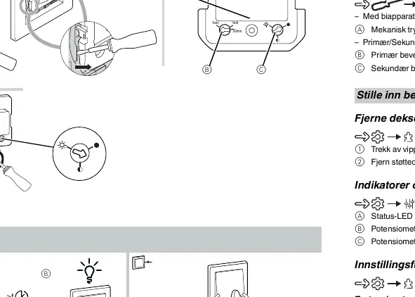
Ensure the device is disconnected from the circuit during insulation resistance tests. The wiring requires connection to the installation network. Refer to the wiring diagram for proper terminal connections, including the extension unit (mechanical push-button).
Operating Modes
- Automatic Mode: The sensor automatically switches loads on and off based on motion detection and ambient brightness.
- Manual Mode: Loads can be switched on or off locally using the push-button, regardless of ambient brightness.
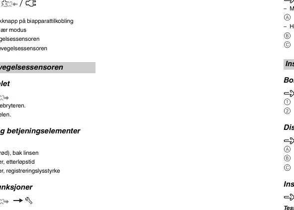
- Secondary Mode: Used to send a trigger command to a primary motion sensor when motion is detected.
Settings
The device features two potentiometers for configuration:
- Detection Brightness: Adjustable between 5 and 500 lux.
- Overtravel Time: Adjustable between 1 second and 30 minutes.
A test mode is available to verify installation and motion detection without switching loads.
Troubleshooting
- If the load does not switch on, increase the detection brightness.
- If the load is permanently switched on, reduce the overtravel time.
Manufacturer information
ELKO AS
Practical help
Common problems
Load does not switch on
Increase the detection brightness setting.
Load is permanently switched on
Reduce the overtravel time setting.
Before use
- Ensure power is disconnected at the circuit breaker before installation.
- Verify wiring against the provided diagram.
- Ensure no light or heat sources interfere with the detection range.
- Check that the extension unit (if used) is a mechanical push-button.
Specs in practice
- Nominal voltage
- AC 230 V, 50 Hz
- Nominal current
- 10 A, cos phi = 0.6
- Overtravel time
- Adjustable from 1 second to 30 minutes
- Detection brightness
- Adjustable from 5 to 500 lux
Images and diagrams
- Wiring diagram shows L (Live) and N (Neutral) connections.
- Extension unit (mechanical push-button) connects to the designated terminal.
- Primary/Secondary mode setup involves connecting multiple sensors.
Model compatibility
- Compatible with ohmic, inductive, or capacitive loads.
- Supports extension units (mechanical push-buttons) with unlimited quantity.
- Maximum cable length for extension unit is 50 m.

Manual page author
Michael Turner
Technical manual editor
Reviews PDF manuals for structure, safety notes, and practical product details so readers can find the right information quickly.