Power / Solar Charge Controllers
User Manual for EPEVER Tracer BP Series MPPT Solar Charge Controller
Quick guide for the EPEVER Tracer BP Series MPPT Solar Charge Controller. Includes wiring instructions, LED indicator meanings, load working modes, protection features, and troubleshooting steps.
Table of contents
Quick Guide from the Manual
The EPEVER Tracer BP series is an MPPT solar charge controller designed for various battery types, including lead-acid and lithium. Crucial Wiring Sequence: Always connect components in the following order: 1. Battery, 2. PV (Solar Module), 3. Load. When disconnecting, reverse this order. Ensure a fast-acting fuse is installed on the battery positive line within 150mm of the battery.
Product Overview
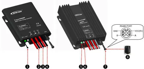
The controller features an aluminum housing for cooling and is IP68 waterproof. Key components include the temperature sensor, PV input, battery input, load output, and an RS485 communication port. The RS485 port provides a 5VDC/150mA power supply and requires the waterproof cap to be installed when not in use.
Wiring and Installation
Installation must be performed in a non-corrosive, non-flammable environment. Connect the battery first to power the controller, then connect the PV array, and finally the load. Ensure all connections are tight to prevent overheating. The controller includes a load self-test function that turns the load ON for 10 seconds after power-up.
LED Indicators
The controller uses LED indicators to show system status:
- PV Indicator (Green): Solid means normal operation (low voltage/no charging), OFF means no PV voltage (night), Slowly Flashing (1Hz) means charging, Fast Flashing (4Hz) means PV overvoltage.
- Battery Indicator (Green/Orange/Red): Solid Green means normal, Slowly Flashing Green means full charge, Fast Flashing Green means overvoltage. Orange means under voltage. Red means over-discharged. Fast Flashing Red indicates overheating or lithium battery low temperature.
- System Error: If both charging and battery indicators flash simultaneously, there is a system voltage error.
Load Working Modes
The controller supports four load working modes:
- Manual Mode: Default ON.
- Light ON/OFF: Automatically turns on/off based on light levels.
- Light ON + Timer: Turns on based on light levels and runs for a set duration.
- Real-time Control: Controls load ON/OFF time via a real-time clock.
Note: In Light ON/OFF and Light ON/Timer modes, the load turns on after a 10-minute delay.
Protection Features
The controller includes comprehensive protections: PV over current, PV short circuit, PV reverse polarity, battery reverse polarity, battery over voltage, battery over discharge, battery overheating, lithium battery low temperature, load overload, and load short circuit. In case of load overload or short circuit, the controller attempts to reconnect 5 times with increasing delays.
Troubleshooting
If the charging indicator is off during the day, check PV and battery connections. If there is no LED indicator, measure battery voltage; it must be at least 8.5V to start. If the battery LED flashes red, the battery is overheating; the system will turn off until the temperature drops below 50 degrees Celsius. For load output issues, check for overload or short circuits and restart the controller.
Technical Specifications
The Tracer BP series supports 12V/24V systems (auto-detect for lead-acid, manual for lithium). The input voltage range is 8.5V to 32V. The enclosure is rated IP68. Operating temperature ranges from -40 degrees Celsius to +60 degrees Celsius (or +50 degrees Celsius depending on the model).
Practical help
Common problems
LED Charging indicator off during daytime
Check that PV and battery wire connections are correct and tight.
No LED indicator
Battery voltage may be below 8.5V. Measure with a multi-meter.
Battery LED fast flashing green
Battery over voltage. Disconnect the PV array.
Load is not outputting
Check for overload or short circuit. Reduce load, restart controller, or wait for one night-day cycle.
Before use
- Ensure battery voltage is between 8.5V and 32V.
- Install a fast-acting fuse on the battery positive line (1.25 to 2 times rated current).
- Verify the PV open circuit voltage does not exceed the controller limit.
- Ensure the installation environment is not humid, salty, or corrosive.
- Confirm the battery type is compatible (Lead-acid or Lithium).
Specs in practice
- MPPT Technology
- Advanced Maximum Power Point Tracking to increase charging efficiency.
Images and diagrams
- Wiring sequence: Connect Battery first, then PV, then Load.
- LED indicators provide status for PV, Battery, and system errors.
Model compatibility
- Supports Lead-acid (Sealed, Gel, Flooded) and Lithium batteries.
- Lithium battery requires manual setting as it is not automatically identified.

Manual page author
Emily Carter
User documentation editor
Prepares concise manual descriptions and highlights the most useful setup, operation, and maintenance information for readers.