Software / Apps Services
User Manual for Falcon MPPT Solar Controller 12/24V
Quick guide for the Falcon MPPT Solar Controller (Model FN-MPPT2050-BT). Includes installation steps, wiring diagrams, LED status indicators, and troubleshooting for 12V/24V solar systems.
Table of contents
Manual images
Click an image to enlargeQuick guide from the manual
This solar charge controller uses advanced Maximum Power Point Tracking (MPPT) technology to optimize energy harvest from solar panels. The device features automatic 12V/24V recognition and supports various battery types including Liquid, Gel, AGM, and Lithium. Always install the controller in a well-ventilated area and follow the specific wiring sequence: connect the battery first, then the solar modules.
Safety instructions
- Danger of explosion: Avoid sparking and short-circuiting battery terminals.
- Ventilation: Install in a well-ventilated place to prevent overheating.
- Wiring: Always use fuses or circuit breakers on connection cables.
- Handling: Do not disassemble the controller; there are no user-serviceable parts inside.
- Protection: Protect solar modules from incident light during installation (e.g., cover them).
Installation
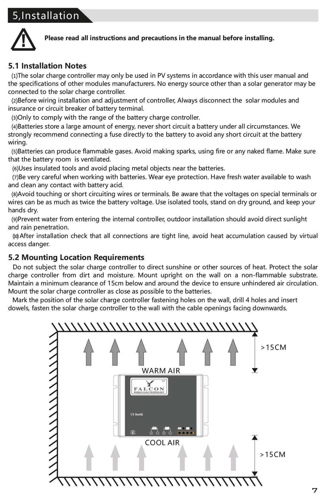
Mounting: Mount the controller upright on a non-flammable surface. Ensure a minimum clearance of 15cm below and around the device to allow for air circulation. Keep the controller as close to the batteries as possible.
Wiring sequence:
- Connect the battery: Ensure correct polarity. If the system is 12V, battery voltage must be 5V-15.5V. If 24V, it must be 20V-31V.
- Connect the solar module: Ensure the solar module is protected from light. Connect to the solar module terminals with correct polarity.
- Final work: Tighten all connections and remove debris.
Bluetooth and operation
The controller supports Bluetooth communication via an Android/iOS mobile app. It allows for wireless monitoring and parameter adjustment. The controller automatically detects battery types and manages charging stages: MPPT, Boost, Equalization, and Float.
LED indications and troubleshooting
The LED display provides real-time status updates:
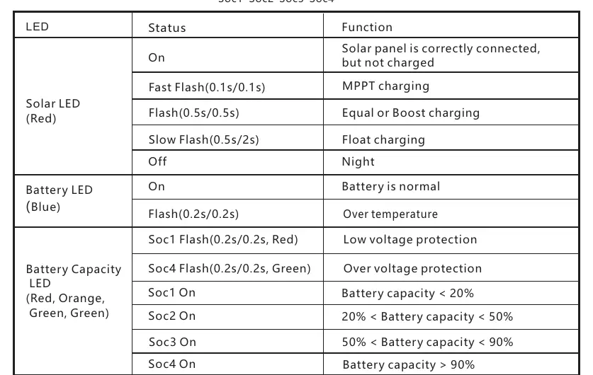
- Solar LED (Red): Indicates charging status (Fast flash = MPPT, Slow flash = Float, Off = Night).
- Battery LED (Blue): Indicates battery health.
- Battery Capacity LED: Shows charge level (Soc1 to Soc4).
If a fault occurs, such as "High voltage at battery terminal" or "Communication failure," check the wiring, ensure the battery voltage is within the operating range, or reconnect the Bluetooth device.
Technical data
- System voltage: 12/24V automatic recognition
- Max charging current: 20A
- Max conversion efficiency: 98.0%
- Communication: BLE
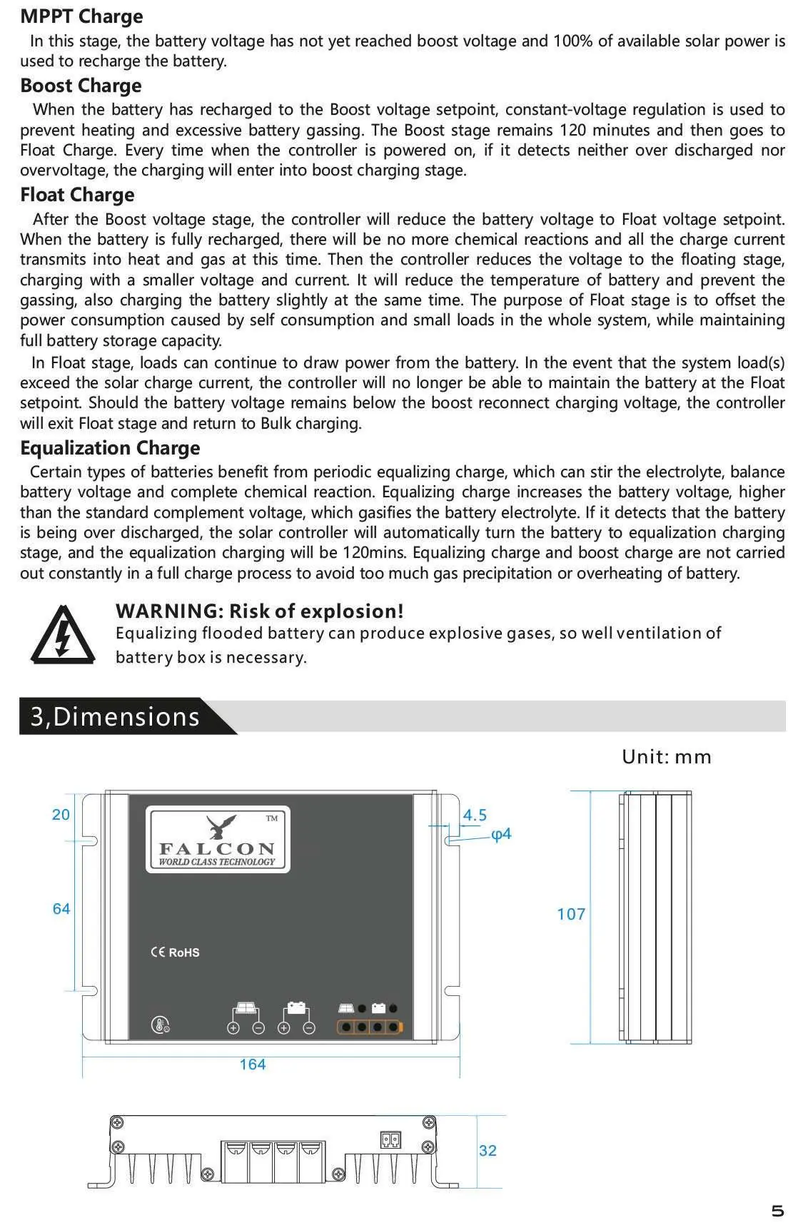
- Dimensions: 164 x 107 x 32 mm
- Protection degree: IP54
Manufacturer information
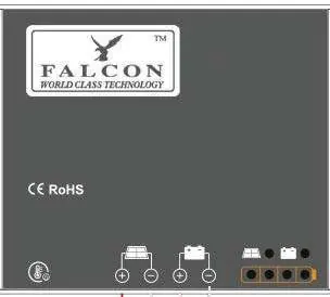
Falcon Electronics
Practical help
Common problems
High voltage at battery terminal
Check if other sources are overcharging the battery. If not, the controller may be damaged.
Can't recognize Bluetooth
Disconnect the battery for about 1 minute and reconnect the Bluetooth device.
Battery can't be charged during daytime
Check solar panels and connection wires for damage or loose connections.
Can't recognize system voltage
Charge or discharge the battery so the voltage is within the normal operating range (5-15.5V or 20-31V).
Before use
- Verify battery voltage is within 5-15.5V (for 12V system) or 20-31V (for 24V system).
- Ensure the installation location is well-ventilated and free from direct heat sources.
- Install a fuse directly to the battery to prevent short circuits.
- Use insulated tools and wear eye protection when working with batteries.
- Ensure wire diameter is appropriate for the 20A current (5/10 mm²/AWG recommended).
Specs in practice
- 12/24V Automatic Recognition
- The controller automatically detects the nominal voltage of the connected battery bank.
- 20A Max Charging Current
- The maximum current the controller can deliver to the battery.
- MPPT Technology
- Maximum Power Point Tracking optimizes solar panel output, increasing efficiency by up to 30% compared to PWM.
Images and diagrams
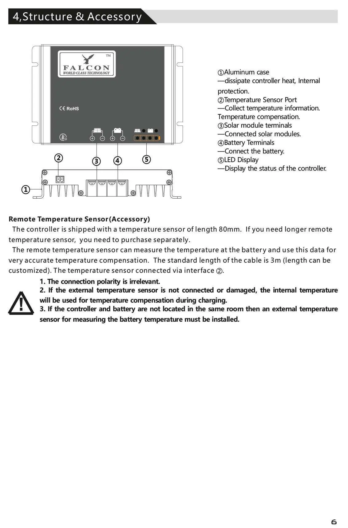
- The wiring diagram shows the correct sequence: Battery must be connected to the middle terminals first, followed by the solar panels to the left terminals.
- The mounting diagram illustrates the required 15cm clearance above and below the unit for proper airflow.
Model compatibility
- Compatible with Liquid, Gel, AGM, and Lithium batteries.
- Bluetooth app is available for Android and iOS.
- Not suitable for non-solar energy sources.

Manual page author
Emily Carter
User documentation editor
Prepares concise manual descriptions and highlights the most useful setup, operation, and maintenance information for readers.