Automotive / ECU Tuning
Installation Manual for Evolution Powersports ECU Power Flash for Can-Am Maverick X3
A comprehensive installation and adjustment guide for Evolution Powersports ECU Power Flash kits for the Can-Am Maverick X3. This manual covers performance specifications for Stages 1 through 5, detailed wastegate adjustment procedures...
Table of contents
Manual images
Click an image to enlargeQuick Guide to ECU Programming
This document provides installation and tuning instructions for the Evolution Powersports ECU Power Flash for 2020 Can-Am Maverick X3 Turbo RR vehicles. The system offers various performance stages (1 through 5x85), each requiring specific fuel octanes and hardware configurations (such as stock exhaust or race bypass pipes). Always ensure your vehicle meets the hardware requirements for the specific stage you are installing.
Performance Features
- Revised intercooler fan settings.
- Left foot braking enabled for 2-foot operation.
- Improved boost and throttle response.
- Increased speed limits in high and low gear.
- Torque limits removed in high and low gear.
- High and low gear rev limit increased to 9000 RPM.
- V-Max raised.
- Engine fan activation temperature set to 185 degrees.
- Race Start feature allows engine start without pressing the brake.
Wastegate Adjustment Procedure
Proper wastegate adjustment is critical for achieving target boost pressures. Required tools: 10mm open-end wrench, Mityvac (MV8255), and a flat-head screwdriver.
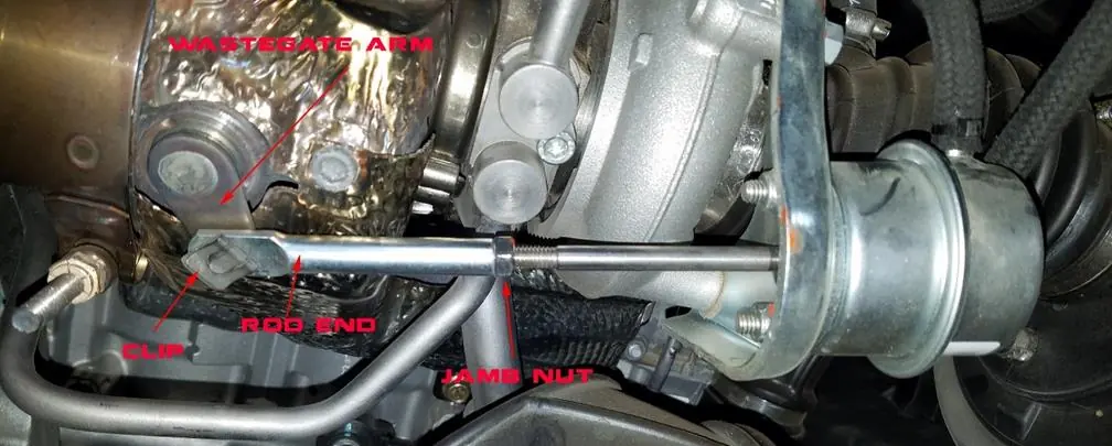
- Remove the panel between the seats to access the turbocharger.
- Use a flat-head screwdriver to remove the retaining clip holding the wastegate actuator rod to the wastegate arm. Do not lose this clip.
- Loosen the jamb nut on the wastegate rod using a 10mm wrench. If the nut is too tight, you may need to remove the wastegate actuator from the turbo.
- Screw the rod end clockwise to shorten the arm and raise crack pressure, or lengthen it to lower crack pressure. Verify crack pressure using a Mityvac.
- Check the pressure three times to ensure accuracy.
- Reattach the rod end to the wastegate arm.
- Reinstall the clip and tighten the jamb nut.
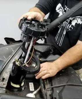
Fuel Pump Installation
Note: Syphon all fuel out of the tank before starting. The fuel pump relay harness must be installed before powering up the dash or starting the vehicle to prevent ECU damage.
- Remove the plastics covering the fuel tank.
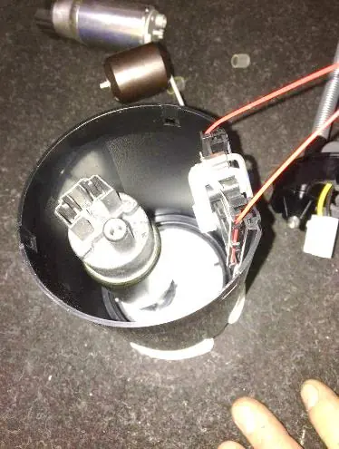
- Unplug the electrical connector at the top of the pump.
- Unhook the fuel hose by removing the red clip, pushing down on the fitting, and lifting it off the assembly.
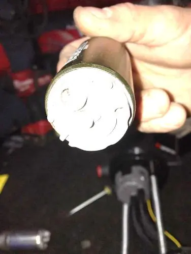
- Rotate the pump assembly cap counterclockwise and remove the assembly.
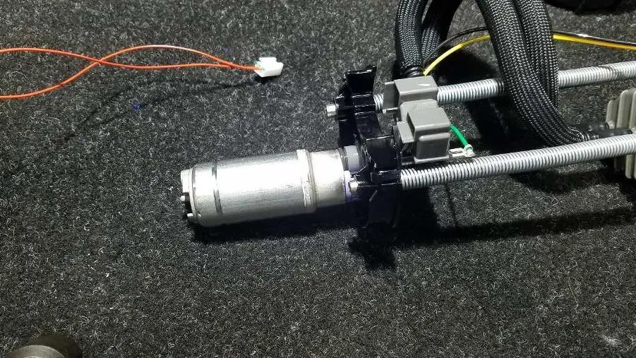
- With the pump on a workbench and drained of fuel, press the tabs to release the housing covering the tank.
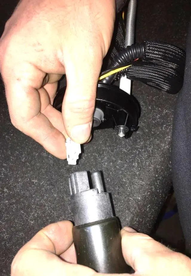
- Pull the pump out of its seat and disconnect the electrical connection.
- Install the new EVP fuel pump into the plastic housing. Ensure it is oriented correctly so it drops into place and does not rotate.
- Plug the electrical connection into the pump.
- Align the tabs and reinsert the cap into the housing. Do not force it; if it does not fit with moderate pressure, recheck the alignment.
- Reinstall the pump assembly.
- Install the EVP Plug N Play Fuel Pump Relay Harness.
- Connect the yellow wire with the ring terminal and the relay to a bolt securing the fuel pump protector strap to the frame. Ensure the terminal is grounded to the frame.
- Replace the OEM fuel pump fuse with the supplied 20-amp fuse in location F5.
Legal and Emission Compliance
This product is exempt from emission standards under 40 C.F.R. § 1051.620. It is sold exclusively for use on EPA-certified, purpose-built, non-road vehicles used solely for closed-course competition or racing. It is not intended for recreational use on public highways or public rights-of-way.
Manufacturer information
Evolution Powersports LLC
Practical help
Common problems
Wastegate rod is too tight to adjust
You may need to remove the wastegate actuator from the turbo to loosen the jamb nut.
Fuel pump cap does not fit back into the housing
Do not force it. Recheck the alignment of the tabs and ensure fuel lines and electrical connections are not obstructing the fit.
Engine will not start or ECU damage
Ensure the fuel pump relay harness is installed before powering up the dash or starting the vehicle.
Before use
- Syphon all fuel out of the tank before starting fuel pump installation.
- Verify you have a 10mm open-end wrench, Mityvac (MV8255), and a flat-head screwdriver.
- Confirm your vehicle meets the hardware requirements (e.g., exhaust type) for the specific ECU stage.
- Ensure the fuel pump relay harness is ready for installation.
Specs in practice
- Spark Plug Gap
- The recommended gap setting for the spark plugs to ensure optimal combustion.
Images and diagrams
- The wastegate adjustment diagram identifies the wastegate arm, rod end, clip, and jamb nut.
- Fuel pump installation photos illustrate the removal of the pump assembly, housing tabs, and electrical connections.
Model compatibility
- Product is for closed-course, non-road competition/racing vehicles only.
- Not for use on public highways or recreational areas.
- Requires specific hardware (e.g., High Flow Muffler) for higher stages (3R, 4x100, 5, 5x85).

Manual page author
Michael Turner
Technical manual editor
Reviews PDF manuals for structure, safety notes, and practical product details so readers can find the right information quickly.