Automotive / ECU Tuning
Installation Manual for Evolution Powersports X3 Boost Recirculating Valve 2.0 Kit
Quick installation guide for the Evolution Powersports X3 Boost Recirculating Valve 2.0 Kit (100FC0125). Includes parts list, step-by-step installation instructions, and hose routing diagrams.
Table of contents
Manual images
Click an image to enlargeQuick Guide from the Manual
This document provides installation instructions for the Evolution Powersports X3 Boost Recirculating Valve (BRV) 2.0 Kit. The installation involves removing the intercooler and charge tubes, installing the provided fittings, routing new hoses, and connecting vacuum lines. Please note that the installation procedure varies slightly depending on whether your vehicle has a catch can installed.
Included Parts
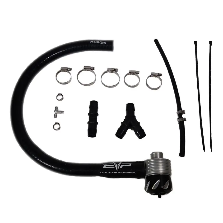
- (1) EVP 2.0 Boost Recirculating Valve
- (1) EVP BRV Silicone Hose
- (1) Manifold Port Adaptor
- (3) 20-32mm Worm Drive Clamps
- (1) “Y” 3/4” x 3/4” x 3/4” Fitting
- (1) Straight 3/4” x 3/4” Fitting
- (2) 25-40mm Worm Drive Clamps
- (2) Zip Tie
- (1) 12” BRV Vacuum Hose
- (2) 13.3mm Pinch Clamps
Required Tools
- 8, 10, 11mm Socket
- Flat Blade Screwdriver
- Side Cutters
Installation Steps
- Remove intercooler: Start by removing the intercooler from the vehicle.
- Remove charge tubes: Remove both charge tubes from the intercooler and fully remove the charge tube on the turbo.
- Remove crank case vent line: Remove the crank case vent line and fitting from the v-flow intake. Note: If you have a catch can installed, the v-flow will be plugged off and the crank case vent line will be routed to the catch can.
- Install Y fitting: Install the Y fitting into the v-flow intake. Note: Only perform this step if you do NOT have a catch-can installed. If you have a catch can installed, use the 3/4"-3/4” straight fitting instead.
- Route hoses: Route the Boost Recirculating Valve hose over the bottom charge tube going to the throttle body and connect it to the v-flow if you have a catch can installed. If you do not have a catch can installed, route the crank case vent hose underneath the charge tube and the Boost recirculating valve hose over the charge tube. Connect both hoses to the “Y” fitting leading into the v-flow. Ensure hoses are not pinched by the intercooler. If adjustments are needed, loosen the v-flow and spin it to change the angle of the hoses.
- Connect BRV: Connect the base of the BRV into the charge tube and tighten down with a 25-40mm worm drive.
- Connect silicone hose: Connect the 1” side of the EVP hose to the BRV and clamp it with the last 25-40mm worm drive. Connect the other end of the silicone hose to the V Flow.
- Connect vacuum line: Connect the 3mm vacuum end to the BRV port located on the cap using a 13.3mm pinch clamp. Route the 6mm vacuum line down to the plenum. If you do not have a port adaptor mounted on the plenum, remove the Torx screw and the plug. Install the EVP port adaptor and fasten with the OEM Torx screw. Connect the 6mm line to the plenum and fasten with a 13.3mm pinch clamp.
- Reinstall intercooler: Reinstall the intercooler, connect both charge tubes to the intercooler, reconnect the fan harness, and tighten all connections.
Important Legal Information
This product is exempt from emission standards and related requirements of 40 C.F.R. § 1051 as provided by 40 C.F.R. § 1051.620, and California law. This product is sold only for use in connection with EPA certified, purpose-built, nonroad vehicles used solely for closed course, nonroad competition/racing and not used for any recreational purpose or on public highways. For further assistance, call Tech Support at (715) 247-3862.
Manufacturer information
Evolution Powersports LLC
Practical help
Common problems
Hoses getting pinched by the intercooler.
Ensure hoses are routed correctly. If adjustments are needed, loosen the v-flow and spin it to change the angle of the crank case/boost recirculating hoses.
Unsure about catch can configuration.
If a catch can is installed, the v-flow is plugged off and the crank case vent line goes to the catch can; use the 3/4"-3/4" straight fitting instead of the Y fitting.
Before use
- Verify all parts from the included parts list are present.
- Ensure you have the required tools: 8, 10, 11mm sockets, flat blade screwdriver, and side cutters.
- Determine if your vehicle has a catch can installed to choose the correct fitting configuration.
Images and diagrams
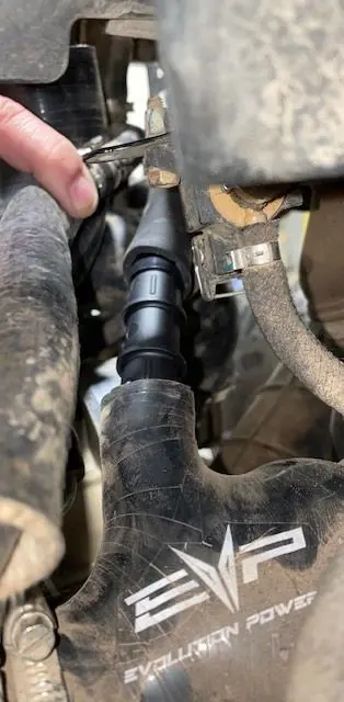
- Figure 1: Shows the installation of the Y fitting into the v-flow intake.
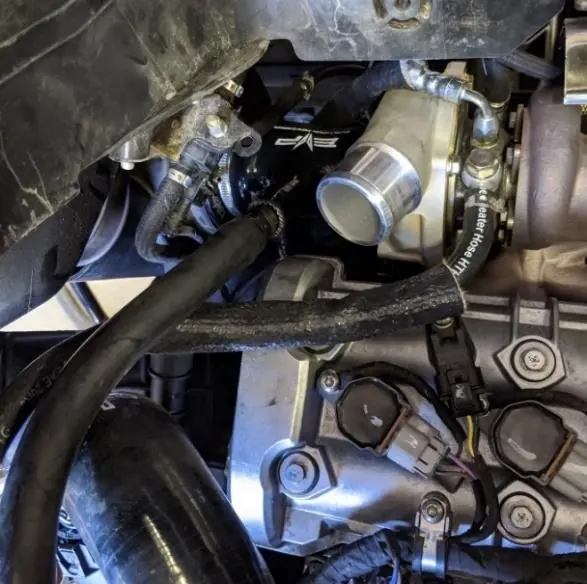
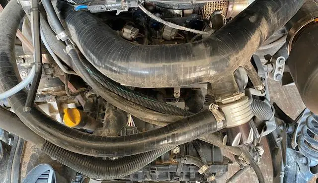
- Figure 2 & 3: Illustrate the routing of the Boost Recirculating Valve hose and crank case vent hose.
- Figure 4 & 5: Show the final connection points for the BRV and crank case vent hoses to the v-flow.
- Figure 6: Details the connection of the vacuum line to the plenum.
Model compatibility
- Designed for use in connection with EPA certified, purpose-built, nonroad vehicles used solely for closed course, nonroad competition/racing.
- Not for use on public highways or recreational purposes.

Manual page author
Emily Carter
User documentation editor
Prepares concise manual descriptions and highlights the most useful setup, operation, and maintenance information for readers.