General / Other Manuals
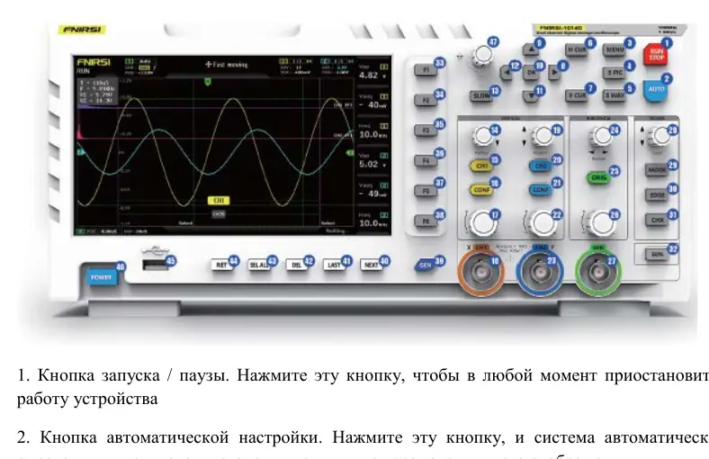
FNIRSI 1014D Digital Oscilloscope Operation Manual
Comprehensive operation manual for the FNIRSI 1014D 2-channel 100 MHz digital oscilloscope, covering setup, signal measurement, safety, and troubleshooting.
Table of contents
Product Overview
The FNIRSI 1014D is a versatile, two-channel desktop digital oscilloscope combined with a built-in DDS signal generator. Designed for R&D and maintenance, it features a 1 GSa/s real-time sampling rate and a 100 MHz analog bandwidth. The device is equipped with a 7-inch high-definition LCD display (800x480 resolution) and offers a user-friendly interface for waveform analysis.
Key Features
The oscilloscope includes a full-featured trigger system (single, normal, automatic) suitable for both periodic analog and aperiodic digital signals. The integrated DDS signal generator supports 14 standard waveforms and customizable interrupted signals. Users can store up to 1000 screenshots and 1000 waveform data groups in the 1GB internal memory. Advanced features include cursor measurements, FFT analysis, and Lissajous figure display for comparing signal amplitude, frequency, and phase.
Safety and Operation
Safety is paramount when operating the device. Always use the original power supply and ensure proper grounding. When using two channels, the ground clips of both probes must be connected together to avoid short-circuiting the motherboard. The BNC input can withstand up to 400V, but exceeding this limit is strictly prohibited. For high-frequency or high-voltage measurements, use appropriate 10x or 100x probes to prevent signal attenuation and protect the device.
Measurement and Maintenance
The device allows for easy waveform capture and saving with a single click. Users can perform various measurements, including battery voltage, PWM signals, and inverter output. The interface provides intuitive controls for vertical and horizontal scaling, trigger level adjustment, and cursor positioning. Maintenance is minimal; keep the device in a dry, dust-free environment and clean it only with a soft, dry cloth. Avoid exposure to corrosive substances, water, or extreme temperatures.
Troubleshooting
If the device fails to power on, check the power connection. If no waveform appears, ensure the pause button is not active and verify the signal source. For zero voltage or frequency readings, adjust the vertical sensitivity and time base, or use the auto-set function. If the signal is unstable, adjust the trigger level or enable the automatic 50% trigger setting. For detailed signal analysis, ensure the probe attenuation settings on the oscilloscope match the physical probe switch.
Manufacturer information
Shenzhen FNIRSI Technology Co., Ltd.
Practical help
Common problems
Device does not turn on
Check power cable connection and power outlet. Try a different charger.
No waveform on screen
Check if pause is active, press [AUTO], or verify the signal source and probe connection.
Voltage or frequency reads 0
Adjust vertical sensitivity and time base, or press [AUTO] to ensure a full waveform is displayed.
Waveform is unstable/jittery
Adjust the trigger level (green arrow) or enable 'Automatic 50%' in the menu.
Signal above 5MHz is heavily attenuated
Switch both the probe and the oscilloscope settings to 10x mode.
Before use
- Ensure the device is in a dry, dust-free environment.
- Use only the original power supply.
- Connect ground clips together when using two channels.
- Verify probe attenuation setting (1x/10x/100x) matches the oscilloscope setting.
- Ensure the probe is properly connected to the BNC input.
- Check that the signal source is active.
- Perform baseline calibration if the baseline and arrow do not match.
Specs in practice
- Sampling Rate
- 1 GSa/s real-time sampling for accurate signal capture.
- Trigger Modes
- Auto, Normal, and Single modes for capturing various signal types.
- Input Voltage
- BNC input withstands up to 400V.
Images and diagrams
- 1-7: Status indicators, grid, and channel waveforms.
- 8-10: Horizontal time base settings and sensitivity.
- 11-17: Trigger status and measurement columns (Vpp, Vavg, Freq).
- 18-23: Channel identification, coupling (AC/DC), and vertical sensitivity.
- 25-29: Trigger settings including mode, edge, and level.
Model compatibility
- Use only probes with 100 MHz bandwidth or higher.
- 100x probes are required for high-voltage measurements (e.g., 220V mains).
- The device is not waterproof; avoid moisture.
- Compatible with standard USB for data transfer to PC.

Manual page author
David Miller
Documentation analyst
Organizes user manual content into clear summaries, with attention to model details, product context, and everyday usability.