Automotive / Parts & Accessories
Timing Drive Components Repair Guide for 2008 Ford Fusion 2.3L
A comprehensive repair and maintenance guide for the timing drive components of the 2008 Ford Fusion 2.3L engine. Includes step-by-step removal and installation procedures, torque specifications, and critical safety warnings for engine...
Quick answers from the manual
Quick answer
- This document provides the official workshop procedure for removing and installing the timing drive components on a 2008 Ford Fusion 2.3L engine, including torque specifications and critical safety warnings. p. 1, 6
Key actions
- Compress the timing chain tensioner p. 1, 5
- Tighten camshaft sprocket bolts p. 6
Maintenance and reset
- Release the tensioner piston p. 5
Technical specifications
| Parameter | Value | Meaning | Pages |
|---|---|---|---|
| Timing chain guide/tensioner bolt torque | 10 Nm (89 lb-in) | Tightening torque | p. 3, 5 |
| Camshaft sprocket bolt torque | 72 Nm (53 lb-ft) | Tightening torque | p. 6 |
Where to find it in the PDF
- Removal Procedure p. 1, 2, 3
- Installation Procedure p. 3, 4, 5, 6
Table of contents
Manual images
Click an image to enlargeImportant Safety and Preparation
Before beginning any work on the timing drive components, observe the following critical warnings to prevent severe engine damage:
- Special Tools Required: Do not loosen or remove the crankshaft pulley bolt without first installing the required special service tools. The crankshaft pulley and timing sprocket are not keyed and are held together by friction.
- Engine Locking: The crankshaft and camshafts must be locked in place using special service tools before any repair requiring the loosening or removal of the crankshaft pulley bolt.
- Cleanliness: During engine repair, cleanliness is extremely important. Any foreign material entering oil passages, coolant passages, or the oil pan can cause engine failure.
- Camshaft Alignment Plate: This tool is for alignment only. Do not use it to prevent engine rotation, as this can result in engine damage.
Removal of Timing Drive Components
- With the vehicle in NEUTRAL, position it on a hoist.
- Remove the engine front cover.
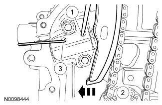
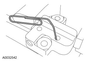
- Compress the timing chain tensioner:
- Using a small pick, release and hold the ratchet mechanism.
- While holding the ratchet mechanism in the released position, compress the tensioner by pushing the timing chain arm toward the tensioner.
- Insert a paper clip into the hole to retain the tensioner.
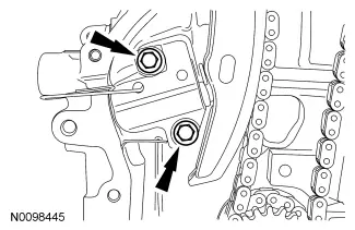
- Remove the 2 bolts and the timing chain tensioner.
- Remove the timing chain tensioner arm.
- Remove the timing chain.
- Remove the 2 bolts and the timing chain guide.
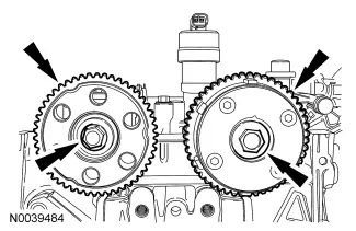
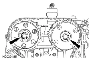
- Using the flats on the camshaft to prevent rotation, remove the bolt and the exhaust camshaft sprocket.
- Using the flats on the camshaft to prevent rotation, remove the bolt and the camshaft phaser and sprocket.
Installation of Timing Drive Components
- Install the camshaft sprockets and the bolts. Do not tighten the bolts at this time.
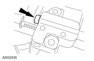
- Install the timing chain guide and the 2 bolts. Tighten to 10 Nm (89 lb-in).
- Install the timing chain.
- Install the timing chain tensioner arm.
- If the timing chain tensioner plunger and ratchet assembly are not pinned in the compressed position, compress the plunger using the edge of a vise. Do not compress the ratchet assembly itself, as this will damage it.
- Using a small pick, push back and hold the ratchet mechanism.
- While holding the ratchet mechanism, push the ratchet arm back into the tensioner housing.
- Install a paper clip into the hole in the tensioner housing to hold the ratchet assembly and the plunger in during installation.
- Install the timing chain tensioner and the 2 bolts. Remove the paper clip to release the piston. Tighten to 10 Nm (89 lb-in).
- Using the flats on the camshafts to prevent rotation, tighten the camshaft bolts to 72 Nm (53 lb-ft).
- Install the engine front cover.
Technical Specifications
Ensure all fasteners are tightened to the following specifications:
- Timing chain guide and tensioner bolts: 10 Nm (89 lb-in)
- Camshaft sprocket bolts: 72 Nm (53 lb-ft)
Manufacturer information
Ford Motor Company
Practical help
Common problems
Risk of severe engine damage during pulley removal
Do not loosen the crankshaft pulley bolt without installing special service tools; the components are held by friction and are not keyed.
Damage to ratchet assembly
Do not compress the ratchet assembly directly. Use a vise to compress the tensioner plunger only.
Before use
- Ensure the vehicle is in NEUTRAL
- Position the vehicle on a hoist
- Verify availability of special service tools for locking crankshaft and camshafts
- Ensure a clean working environment to prevent debris from entering oil or coolant passages
Specs in practice
- 10 Nm (89 lb-in)
- Tightening torque for timing chain guide and tensioner bolts
- 72 Nm (53 lb-ft)
- Tightening torque for camshaft sprocket bolts
Images and diagrams
- The manual provides detailed diagrams for the tensioner compression sequence using a pick and paper clip.
- Diagrams illustrate the correct positioning of the timing chain and guides.
- Visual guides show the use of camshaft flats to prevent rotation during bolt removal/tightening.

Manual page author
David Miller
Documentation analyst
Organizes user manual content into clear summaries, with attention to model details, product context, and everyday usability.