Automotive / Engine Components
Toyota 1GR-FE Engine Cylinder Block Disassembly Guide
A comprehensive service and disassembly guide for the Toyota 1GR-FE engine cylinder block. Includes step-by-step removal procedures for components, inspection methods for connecting rod and crankshaft clearances, torque specifications, and...
Quick answers from the manual
Quick answer
- This manual provides the disassembly and inspection procedures for the Toyota 1GR-FE engine cylinder block, including clearance specifications and component removal sequences. p. 1, 2, 3, 4
Key actions
- Measure connecting rod thrust clearance p. 1
- Measure connecting rod oil clearance using Plastigage p. 2
- Remove crankshaft using specified bolt sequence p. 4, 5
Technical specifications
| Parameter | Value | Meaning | Pages |
|---|---|---|---|
| Connecting Rod Thrust Clearance | 0.15 - 0.30 mm | Standard clearance | p. 1 |
| Connecting Rod Oil Clearance | 0.026 - 0.046 mm | Standard clearance | p. 2 |
| Crankshaft Thrust Clearance | 0.04 - 0.24 mm | Standard clearance | p. 4 |
Where to find it in the PDF
- Disassembly and Inspection p. 1, 2, 3, 4
Table of contents
Manual images
Click an image to enlargeImportant Information
This document provides technical procedures for the disassembly and inspection of the Toyota 1GR-FE engine cylinder block. It is intended for qualified mechanics. Always ensure you have the correct tools, including a dial indicator, ridge reamer, piston ring expander, and a torque wrench, before beginning work.
Disassembly Procedures
Follow these steps to disassemble the cylinder block components:
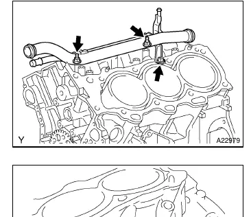
- Water Outlet Pipe No.1: Separate the knock sensor wire, remove the 3 bolts, and remove the pipe.
- Knock Sensor: Disconnect the connectors and remove the 2 bolts and 2 sensors.
- Engine Rear Oil Seal Retainer: Remove the 5 bolts and 2 nuts. Use a screwdriver to pry the retainer from the crankshaft bearing cap.
Inspection and Measurement
Accurate measurement is critical for engine health:
- Connecting Rod Thrust Clearance: Use a dial indicator to measure clearance while moving the rod back and forth. Standard clearance is 0.15 to 0.30 mm (0.0059 to 0.0118 in.).
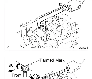
- Connecting Rod Oil Clearance: Use Plastigage to measure. Ensure the protrusion of the connecting rod cap faces the correct direction. Tighten bolts to 25 N·m (250 kgf·cm, 18 ft·lbf) and retighten 90 degrees. Standard oil clearance is 0.026 to 0.046 mm (0.0010 to 0.0018 in.).
- Crankshaft Thrust Clearance: Measure while prying the crankshaft back and forth. Standard clearance is 0.04 to 0.24 mm (0.0016 to 0.0094 in.).
Component Removal
When removing internal components, follow these guidelines:
- Pistons and Connecting Rods: Use a ridge reamer to remove carbon from the cylinder top before pushing the assembly out. Keep bearings, rods, and caps together in the correct order.
- Piston Pins: Gradually heat the piston to approximately 80°C (176°F) before tapping out the pin with a plastic-faced hammer and brass bar.
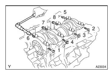
- Crankshaft: Loosen the 8 main bearing cap bolts in the specified sequence.
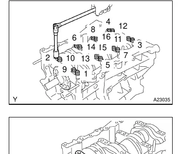
- Main Bearing Caps: Loosen the 16 main bearing cap bolts in the specified sequence. Pry out the caps carefully, pulling up while turning slightly left and right.
- Oil Nozzles: Use a 5 mm socket hexagon wrench to remove the 3 oil nozzles.
Manufacturer information
Toyota Motor Corporation
Practical help
Common problems
Excessive thrust clearance
If clearance exceeds the maximum limit (0.30 mm for connecting rod or crankshaft), replace the thrust washers or the crankshaft.
Bearing replacement
If replacing a bearing, use one with the same number marked on the connecting rod (sizes 1, 2, 3, or 4).
Before use
- Dial indicator for clearance measurements
- Ridge reamer for cylinder carbon removal
- Piston ring expander
- 5 mm socket hexagon wrench
- Torque wrench
- Plastigage for oil clearance measurement
- Plastic-faced hammer and brass bar
Specs in practice
- Standard Connecting Rod Thrust Clearance
- 0.15 to 0.30 mm (0.0059 to 0.0118 in.)
- Standard Connecting Rod Oil Clearance
- 0.026 to 0.046 mm (0.0010 to 0.0018 in.)
- Standard Crankshaft Thrust Clearance
- 0.04 to 0.24 mm (0.0016 to 0.0094 in.)
- Connecting Rod Cap Bolt Torque
- 25 N·m (250 kgf·cm, 18 ft·lbf)
Images and diagrams
- The manual provides specific tightening sequences for main bearing cap bolts (8-bolt and 16-bolt patterns).
- Plastigage usage is illustrated for checking oil clearance on the crank pin.
Model compatibility
- Piston and pin are a matched set.
- Keep bearings, connecting rods, and caps together as matched assemblies.

Manual page author
Emily Carter
User documentation editor
Prepares concise manual descriptions and highlights the most useful setup, operation, and maintenance information for readers.