Electronics / Speakers & Soundbars
Operating Manual for Genelec 1234A Smart Active Monitor
Quick guide for the Genelec 1234A Smart Active Monitor. Learn about installation, flush mounting, GLM software setup, cable connections, and maintenance.
Table of contents
Manual images
Click an image to enlargeQuick Guide
The Genelec 1234A is a high-performance Smart Active Monitor designed for large control rooms. Setup requires the Genelec Loudspeaker Manager (GLM) software for calibration. The system consists of a monitor enclosure and a separate RAM-XL amplifier unit. Ensure the amplifier and enclosure serial numbers match, as they are calibrated as a pair. Proper ventilation and flush mounting are recommended for optimal acoustic performance.
General Description
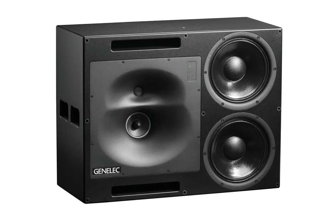
The 1234A system includes a 160-litre enclosure with two 305 mm bass drivers, a 130 mm midrange driver, and a 25 mm treble driver. The midrange and treble drivers are mounted in a rotatable Directivity Control Waveguide (DCW) to allow for horizontal or vertical orientation. The RAM-XL amplifier provides high-precision digital signal processing and overload protection.
Installation and Mounting
Flush mounting is strongly recommended for acoustical reasons. When flush mounting, ensure the enclosure is flush with the wall surface. If using a decorative cloth frame, ensure the material is acoustically transparent. The DCW plate can be rotated by unscrewing the eight M5 fixing screws with a 4 mm Allen key. Ensure the midrange and treble drivers are aligned vertically (treble on top) for optimum stereo symmetry.
Connections
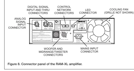
The RAM-XL amplifier connects to the monitor enclosure using the provided 4-pole Speakon cables. Connect the "WOOFER" and "MIDRANGE/TWEETER" sockets on the amplifier to the corresponding sockets on the monitor. The "LED" connector is for the front panel warning light. The "CONTROL NETWORK" RJ45 sockets are used for the GLM network; do not connect these to an Ethernet LAN.
Setup and Use
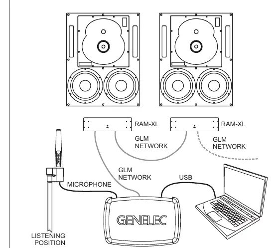
The 1234A is configured using GLM software. Link all monitors and subwoofers in a daisy-chain using CAT5 (RJ45) cables from the GLM Adapter to the "CONTROL NETWORK" connectors. Connect the GLM Adapter to your computer via USB. Place the Genelec measurement microphone at the listening position, pointing upwards at ear height. Follow the GLM software instructions to measure and calibrate the system. You can store settings into the monitors if you do not wish to keep a computer connected.
Operation
The power button on the RAM-XL front panel controls power and testing modes. A short press turns the unit on or off. Intelligent Signal Sensing (ISS) can be activated via GLM software to automatically put the monitor into power-saving standby mode when no audio signal is detected. The front panel light indicates status: green for normal operation, yellow for GLM activity, and red for overload or error conditions.
Maintenance and Safety
Periodically check the protective grille on the cooling fan on the back of the RAM-XL amplifier for blockages and clean with a vacuum cleaner if necessary. Ensure sufficient clearance (at least 100 mm) behind the amplifier for air circulation. Servicing must only be performed by qualified personnel. Do not open the enclosure or amplifier. Ensure the mains connection is earthed.
Manufacturer information
Genelec Oy
Practical help
Common problems
Red warning light on front panel
Indicates overload (analog input too high, digital clipping, or AES/EBU bit errors). Reduce source level or check digital data transmission.
System overheats
Ensure at least 100 mm of space behind the amplifier and that the cooling fan grille is free of blockages.
Monitor does not power on
Check mains connection and ensure the power button has been pressed. If ISS is active, ensure an audio signal is present to wake the monitor.
Before use
- Check all items for damage upon delivery.
- Verify that the RAM-XL amplifier and monitor enclosure serial numbers match.
- Ensure mains voltage is 100-120V or 220-240V.
- Download and install the latest GLM software from genelec.com.
- Ensure 100 mm clearance behind the amplifier for ventilation.
Images and diagrams
- Figure 6 illustrates the GLM network cabling daisy-chain setup.
- Figure 8 details the RAM-XL amplifier connector panel layout.
Model compatibility
- RAM-XL amplifier is calibrated for the specific enclosure it is delivered with; do not mix pairs.
- GLM software is required for system setup and calibration.
- Do not connect GLM network ports to Ethernet LAN.

Manual page author
Emily Carter
User documentation editor
Prepares concise manual descriptions and highlights the most useful setup, operation, and maintenance information for readers.