Electronics / Speakers & Soundbars
Operating Manual for Genelec 1235A Smart Active Monitor
Comprehensive operating manual for the Genelec 1235A Smart Active Monitor. Includes installation guidelines, flush mounting instructions, GLM software setup, cable connection diagrams, and maintenance procedures.
Table of contents
Manual images
Click an image to enlargeQuick Guide from the Manual
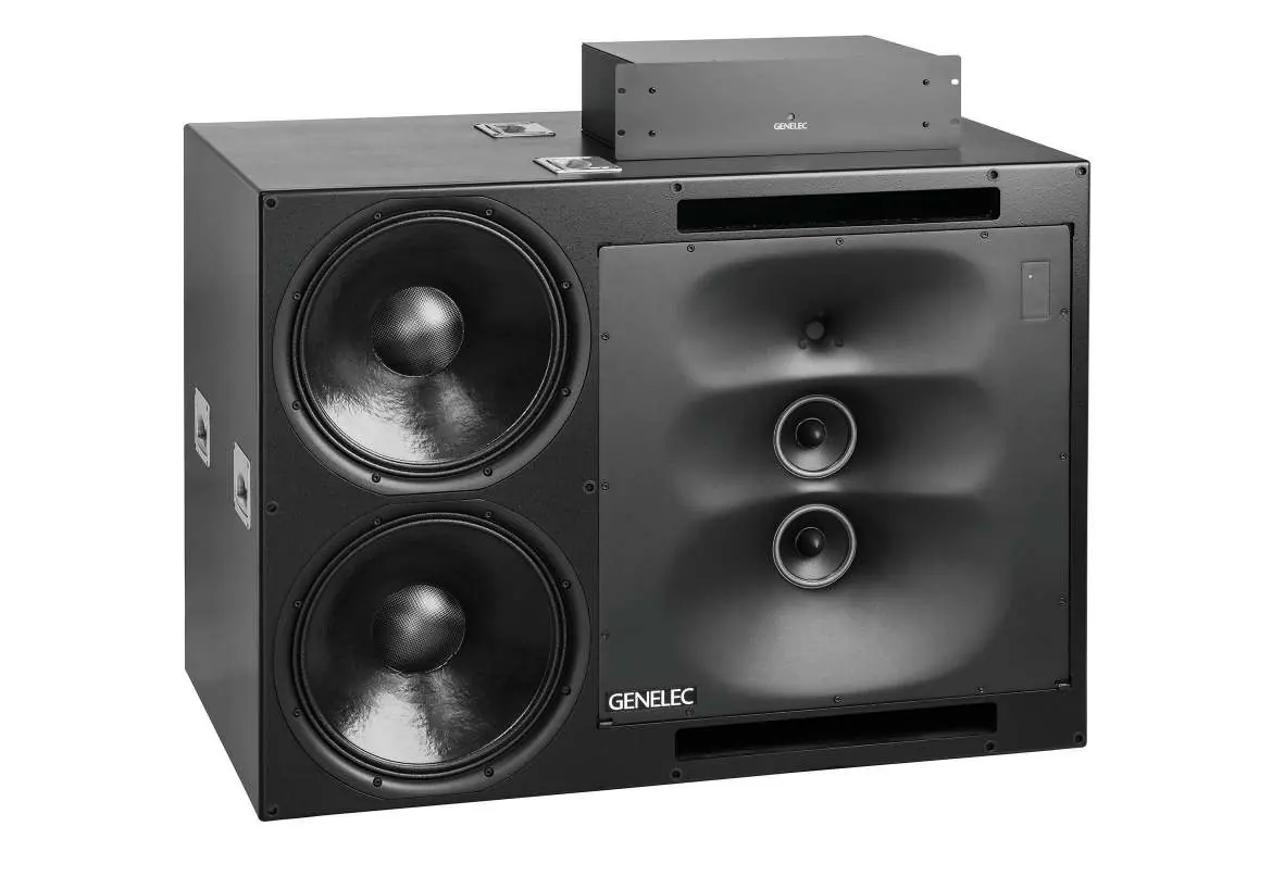
The Genelec 1235A Smart Active Monitor is a high-performance system consisting of a monitor enclosure and a RAM-XL amplifier unit. Setup is performed using the Genelec Loudspeaker Manager (GLM) software. The system is designed for flush mounting in large control rooms to ensure optimal acoustic performance.
Delivery Content
Each 1235A system includes:
- Monitor enclosure
- Individually calibrated RAM-XL amplifier unit
- Mains connecting cable
- RJ45 cable (10m and 5m)
- Two 10m 4-pole Speakon cables
- Allen key
Installation and Mounting
Flush mounting is strongly recommended for acoustical reasons. Ensure the enclosure is flush with the wall surface to prevent diffraction. If using a decorative cloth frame, ensure the material is acoustically transparent and edges are less than 20 mm deep.
Aligning the DCW
The Directivity Control Waveguide (DCW) can be rotated for vertical or horizontal mounting. To rotate:
- Place the monitor in the intended orientation.
- Unscrew the eight M5 fixing screws using a 4 mm Allen key.
- Carefully pull the plate away, rotate it so the midrange and treble drivers are aligned vertically (treble on top), and remount.
Connecting Speaker Cables
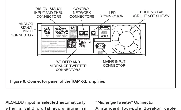
The RAM-XL amplifier is calibrated for the specific enclosure it is delivered with; do not mix amplifier/enclosure pairs. Connect the Speakon cables to the "WOOFER" and "MIDRANGE/TWEETER" sockets on both the amplifier and the monitor. Turn connectors clockwise to lock.
Setup and GLM Software
The 1235A is configured via the GLM software:
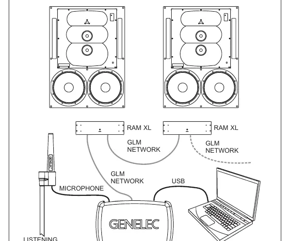
- Link all monitors and subwoofers in a daisy-chain using CAT5 (RJ45) cables from the Network Adaptor to the "CONTROL NETWORK" connectors.
- Connect the GLM Adapter to your computer via USB.
- Place the Genelec measurement microphone at the listening position.
- Download and install the GLM software from www.genelec.com to measure and calibrate the system.
Operation and ISS
The Intelligent Signal Sensing (ISS) feature puts the monitor into power-saving standby mode when no audio signal is detected. This can be activated and configured via the GLM software. The power button on the RAM-XL amplifier also allows for system testing modes (see the manual for specific button press sequences).
Maintenance and Safety
Periodically check the protective grille on the cooling fan on the back of the RAM-XL amplifier for blockages. Clean with a vacuum cleaner if necessary. Ensure the amplifier has sufficient ventilation space (100 mm behind the rear panel) to prevent overheating. Servicing must only be performed by qualified personnel.
Official resources from the manual
Manufacturer information
Genelec Oy
Practical help
Common problems
Red light on front panel
Indicates overload. Turn down the source level or check for bit errors in the AES/EBU digital audio data transmission.
System overheats and stops operating
Ensure free flow of air around the RAM-XL amplifier. Maintain a space of 100 mm behind the rear panel and ensure ambient temperature is 15-35°C.
No sound or incorrect channel assignment
Verify all cable connections and use the GLM software to define channel assignments.
Before use
- Check all items for damage upon delivery.
- Ensure the RAM-XL amplifier is positioned with sufficient ventilation space.
- Verify mains voltage (100-120 VAC or 220-240 VAC).
- Install GLM software from the Genelec website.
- Ensure the DCW is rotated correctly for your mounting orientation (vertical/horizontal).
Specs in practice
- Bass amplifier power
- 2 x 1000 W short term power.
- Frequency response
- 31 Hz – 20 kHz (± 2.0 dB).
- Mains voltage
- 100-120 VAC and 220-240 VAC 50/60 Hz.
Images and diagrams
- Figure 5: Connector panel of the RAM-XL amplifier.
- Figure 6: GLM network cabling diagram.
Model compatibility
- RAM-XL amplifier is calibrated for the specific enclosure it is delivered with; do not mix pairs.
- GLM software is required for system setup.
- Do not connect the Control Network to an Ethernet LAN.

Manual page author
Emily Carter
User documentation editor
Prepares concise manual descriptions and highlights the most useful setup, operation, and maintenance information for readers.