Tools / Generators
Owner's Manual for Generac 60 Hz Air-Cooled Generators
Quick guide for Generac 60 Hz Air-Cooled Generators (8 kW to 22 kW). Includes safety rules, operation, maintenance schedules, troubleshooting, and system diagnosis.
Table of contents
Manual images
Click an image to enlargeQuick guide from the manual
This manual provides essential information for the safe operation and maintenance of Generac 60 Hz Air-Cooled Generators (8 kW to 22 kW). Key procedures include understanding the control panel interface, setting the exercise timer, performing manual transfers, and following the scheduled maintenance plan to ensure reliability.
Safety Rules
Strict adherence to safety rules is required to prevent death, serious injury, or property damage. Key hazards include:
- Exhaust Hazards: Running engines produce carbon monoxide. Install and operate outdoors only.
- Electrical Hazards: Never connect to a building's electrical system without an approved transfer switch installed by a licensed electrician. Verify proper grounding.
- Fire and Explosion: Keep the area around the generator free of debris. Do not obstruct cooling airflow. Use only approved fuel sources.
- Moving Parts: Keep clothing, hair, and appendages away from moving parts.
Generator Overview
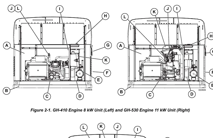
The generator is housed in an all-weather enclosure. Key components include the control panel, battery compartment, fuel regulator, oil fill/dipstick, air filter, and circuit breakers. Refer to the component diagrams in the manual to locate these items for maintenance.
Operation
The control panel allows for three main modes of operation:
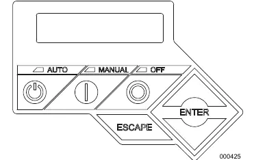
- AUTO: Activates fully automatic system operation, including the exercise timer.
- OFF: Shuts down the engine and prevents automatic operation.
- MANUAL: Cranks and starts the generator. Transfer to standby power will not occur unless utility power fails.
The exercise timer can be configured for weekly, bi-weekly, or monthly operation to keep the engine lubricated and battery charged.
Maintenance
Regular maintenance is critical for performance and warranty compliance. The controller will prompt for Schedule A or Schedule B maintenance.
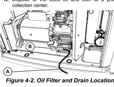
- Engine Oil: Check daily during extended outages. Change oil and filter after the first 25 hours, then according to the schedule. Use SAE 30, 10W-30, or Synthetic 5W-30 depending on temperature.
- Air Cleaner: Inspect and replace as scheduled to ensure proper engine breathing.
- Spark Plugs: Clean, gap, or replace as necessary.
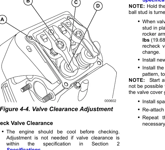
- Valve Clearance: Check and adjust after the first 25 hours and at 400-hour intervals.
- Battery: Inspect posts and cables for corrosion. Maintain charge.
Troubleshooting
If the generator fails to start or shuts down, check the LED indicators on the control panel. Common issues include blown fuses, low oil levels, or tripped circuit breakers. Refer to the System Diagnosis section for specific alarm codes and corrective actions.
Manufacturer information
Generac Power Systems, Inc.
Practical help
Common problems
Engine will not crank
Check for a blown 7.5A fuse, loose/corroded battery cables, or a dead battery.
Engine cranks but will not start
Check fuel supply, fuel valve position, spark plugs, and valve clearance.
Engine runs rough
Check for a plugged air cleaner, defective spark plugs, or incorrect fuel pressure.
No AC output
Ensure the main circuit breaker is in the ON (CLOSED) position.
Before use
- Verify 3 ft. clearance around intake and discharge louvers.
- Ensure all shrubs and tall grasses are removed from the area.
- Check engine oil level.
- Verify battery condition and connections.
- Ensure fuel supply is connected and the valve is open.
- Check for potential water intrusion sources (sprinklers, gutters).
Specs in practice
- Rated Voltage
- 240V AC.
- Rated AC Frequency
- 60 Hz.
- Battery Requirement
- Group 26R, 12V, 540 CCA minimum.
- Operating Temperature
- -20°F (-29°C) to 122°F (50°C).
Images and diagrams
- Figure 2-1/2-2: Identifies key components like oil fill, filter, battery, and control panel.
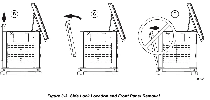
- Figure 3-3: Shows how to open the enclosure and remove the front panel.
- Figure 3-4: Illustrates the control panel interface buttons.
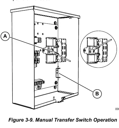
- Figure 3-9: Shows the manual transfer switch operation.
- Figure 4-4: Details the valve clearance adjustment points.
Model compatibility
- Compatible with Liquid Propane (LP) or Natural Gas (NG).
- Cold weather kit recommended for areas where temperatures fall below 32°F (0°C).

Manual page author
Michael Turner
Technical manual editor
Reviews PDF manuals for structure, safety notes, and practical product details so readers can find the right information quickly.